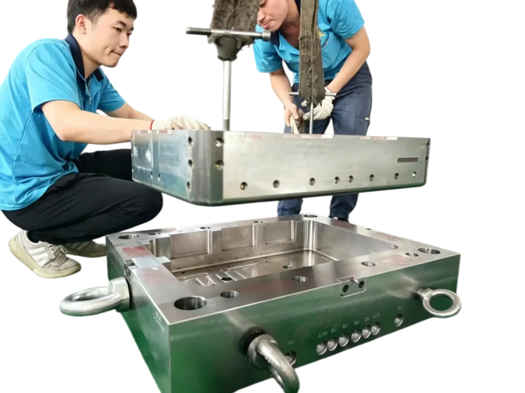
Custom Plastics Injection Mold manufacturer In China
From single-cavity prototype molds to high-volume multi-cavity production tooling — a trusted custom injection mold manufacturer and plastic mold maker, factory-direct from Dongguan, China, shipped worldwide.
| T1 in 15 Days | ±0.005 mm | 1M+ Shots | 20+ Years |
|---|---|---|---|
| Prototype Mold Delivery | Precision Mold Tolerance | Shot Life Guarantee | Mold Manufacturing Experience |
USA
Germany
UK
Italy
Canada
Mexico
Japan
Australia
France
Brazil
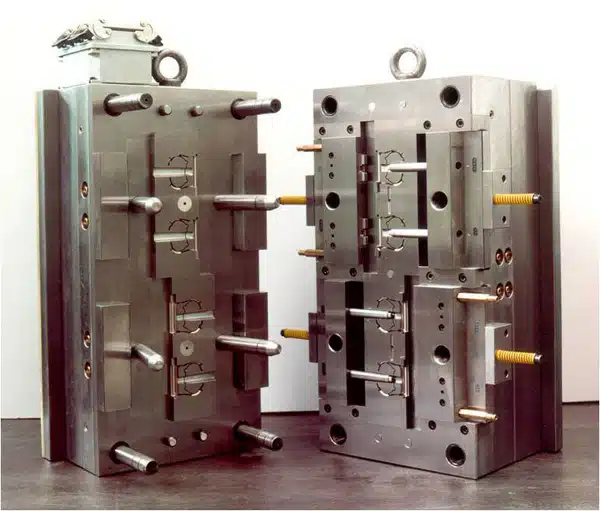
Plastic Injection Mold Types We Specialize In
Not all molds are created equal. From rapid prototype injection molds to high-volume production molds, we help customers choose the right injection mold solution — based on project stage, production volume, tooling budget, and product lifecycle.
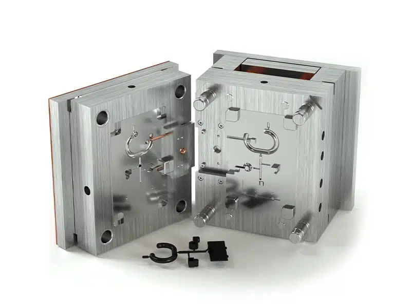
Two Plate Mold
The most common injection mold structure — simple, robust, and cost-effective. The mold splits along a single parting plane, making it easy to maintain and suitable for the vast majority of plastic parts.
- Parting Plane: Single
- Mold Steel Grade: P20 / H13
- Mold Maintenance: low-cost
- Best For: General-purpose parts · Standard geometries · High-volume runs
Three Plate Mold
Features an additional runner plate that automatically separates the gate from the part at ejection. Ideal when the gate location needs to be placed away from the parting line, or when multiple gates are required for better fill.
- Gate Separation: Automatic
- Runner System: Cold runner
- Plates: 3 (A/B plate/runner/
- Best For: Multi-gate parts · Center-gated designs · Improved part aesthetics
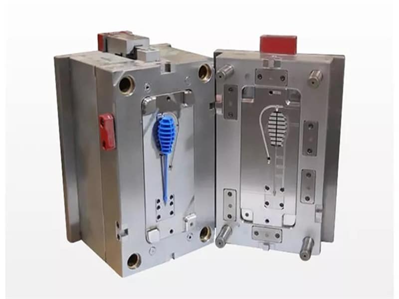
Insert Mold
Metal inserts — such as threaded brass inserts, pins, or terminals — are placed into the mold before injection, and plastic is molded directly around them. The result is a single integrated part with superior mechanical strength.
- Insert Types: Brass / Aluminum
- Strength: Mechanical interlocking
- Insert Loading: Manual/automated
- Best For: Threaded connections · Electrical terminals · Structural housings · Automotive brackets
Overmolding Mold / 2K Mold
Two materials or two colors molded in a single automated process. Overmolding bonds a soft grip layer over a rigid substrate; two-shot molding injects both materials in sequence within the same mold. No assembly required
- Materials: Rigid+Soft (TPU/TPE)
- Color: Dual-color on same part
- Assembly Steps Eliminated: Zero post-mold joining required
- Best For: Soft-grip handles · Waterproof seals· Medical devices
Steel Mold
Steel molds are the industry standard for production tooling. Hardened tool steel delivers exceptional durability, tight dimensional tolerances, and surface finishes that hold up shot after shot — making steel the right choice whenever volume, precision, or material demands it
- Tolerance: ±0.005mm
- Steel Grades: P20 · H13 · S136 · NAK80
- Mold Life: 500,000 – 1,000,000+ Shots
- Best For: High-volume production · Abrasive or corrosive materials · Mirror-finish surfaces · Long-term tooling investment
Aluminum Mold
Aluminum injection molds are machined significantly faster than steel and cost a fraction of the price — making them the ideal choice for prototype tooling, design validation, and low-volume bridge production. Aluminum also conducts heat more efficiently than steel, resulting in faster cooling and shorter cycle times during sampling
- Aluminum Grade: 7075 / 6061
- Mold Life: Up to 5,000+ Shots
- Lead Time: As fast as 7–15 Days
- Best For: Prototype tooling · Design validation · Low-volume runs · Fast market testing
Beryllium Copper Mold (BeCu)
With thermal conductivity up to 10× higher than standard tool steel, BeCu eliminates heat buildup in areas conventional cooling channels can’t reach — deep ribs, thin walls, and high-gloss surfaces. Typically used as core inserts within a steel mold base for maximum effect.
- Mold Life: 500,000+ Shots
- Conductivity: 10× higher than P20 steel
- Application: Core inserts · Deep ribs · Thin walls
- Best For: Good Cooling. High-gloss surfaces · Cycle time reduction
Prototype Tooling
Need to test your part design before committing to full production tooling? Our prototype molds use aluminum or soft steel to get you real injection-molded samples fast — without the cost of a production mold.
- Lead Time: 7-15 Days (T1)
- Mold Life: Up to 5,000 Shots
- Material: Aluminum / Soft Steel
- Best For: Design validation · Functional testing · Pre-production samples
Bridge Tooling
When your design is approved but your production mold isn’t ready yet, bridge tooling keeps your supply chain moving. Simplified steel construction delivers small-batch parts at a fraction of production mold cost.
- Lead Time: 15–30 Days
- Material: Semi-hardened Steel
- Mold Life: 5,000–50,000 Shots
- Best For: Small-batch supply · Market launch · Pre-production inventory
Production Tooling
Built for the long run. Our hardened steel production molds are engineered for high-volume manufacturing — delivering consistent part quality shot after shot, with mold life backed by our guarantee.
- Lead Time: 25–40 Days
- Mold Life: 500,000–1,000,000+ Shots
- Material: P20 / H13 / S136 Hardened Steel
- Best For: Mass production · High-volume OEM supply · Long-term projects
Single Cavity Mold
One mold, one part per cycle. The most straightforward tooling solution — ideal for large parts, low-volume production, or projects where simplicity and lower upfront cost matter most
- Lead Time: 7-40Days (T1)
- Mold Life: Up to 1,000,000 Shots
- Material: Aluminum / Soft Steel/ H13 / S136
- Best For: Small production to max production
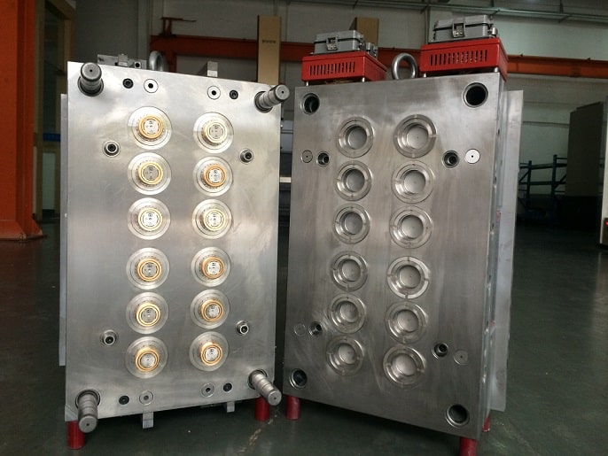
Multi Cavity Mold
Produce multiple identical parts in every single press cycle. Multi-cavity molds dramatically reduce your per-piece cost at scale — the higher the volume, the greater the saving
- Cavities: 2 / 4 / 8 / 16+ (custom)
- Material: H13 / S136 Steel
- Mold Life: 500,000–1,000,000+ Shots
- Best For: High-volume production · Cost reduction programs
Family Mold
Run multiple different part designs from a single mold tool. Family molds are ideal for product assemblies where all components share the same material and color — cutting tooling cost and lead time significantly
- Cavities: 2–8 (custom)
- Mold Life: 500,000–1,000,000+ Shots
- Material: P20 / H13 / S136 Hardened Steel
- Best For: Multi-part assemblies · Matching components · Tooling cost reduction
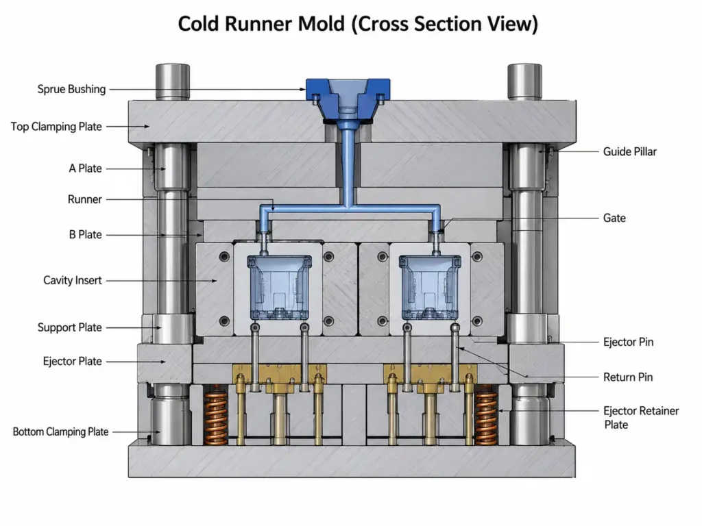
Cold Runner Mold
The most widely used runner system. Material flows through unheated channels and solidifies with each cycle. Lower tooling cost with straightforward maintenance — the right choice for many standard applications.
- Tooling Cost: Lower
- Runner Waste: Yes (regrindable)
- Best For: Standard materials · Cost-sensitive projects · Simple geometries
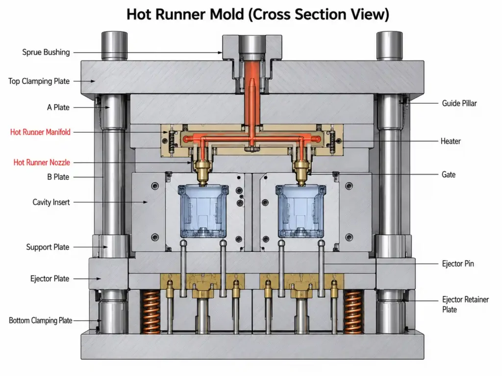
Hot Runner Mold
Heated manifolds keep material molten throughout the runner system, eliminating runner waste entirely. Faster cycle times, better part consistency, and significant material savings at high volumes
- Tooling Cost: Higher
- Runner Waste: Zero
- Best For: High-volume production · Premium materials · Complex multi-gate parts
Not sure which plastic injection mold type, cavity count, runner system, structure, or material is right for your project? Tell us your part design, expected volume, and timeline — our injection mold engineers will recommend the optimal mold configuration within 24 hours, free of charge.
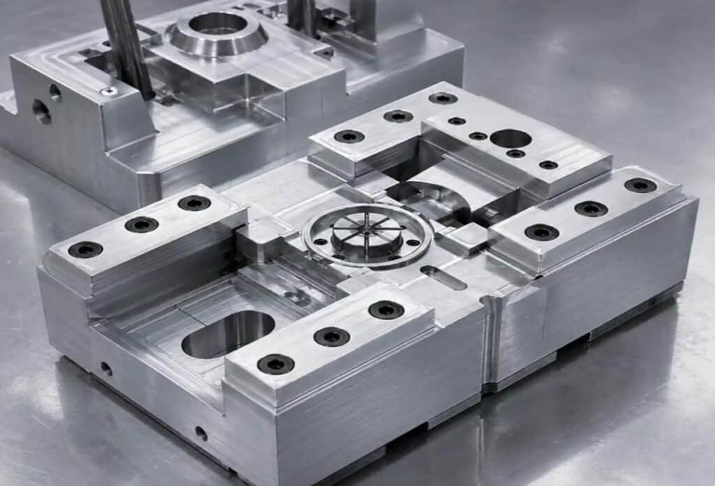
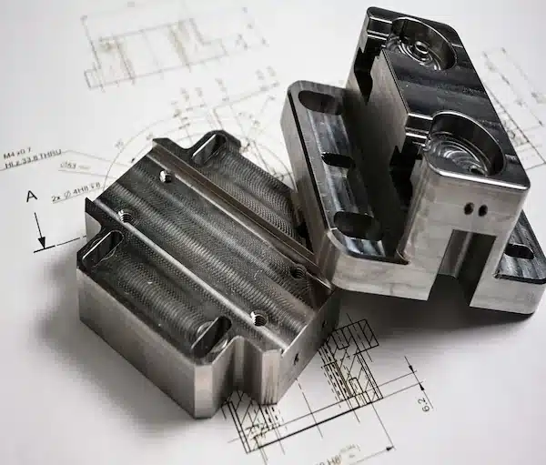
Anatomy of a Mold Plastic Iinjection
A plastic injection mold is far more than a hollow block of steel. Every system inside the mold directly affects your part quality, injection mold cycle time, and tooling cost. Here’s what’s inside every custom injection mold we build.
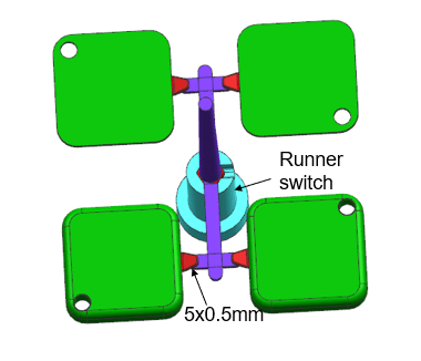
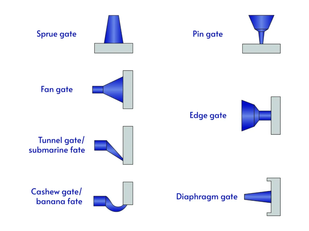
Injection Mold Gate & Runner System
The gate and runner system controls how molten plastic enters the mold cavity. Gate location, size, and type directly influence part aesthetics, structural strength, weld line position, and warpage. We engineer the runner layout and gate design as part of our DFM process — before a single cut is made in steel.
- Gate Types: Edge gate · Submarine gate · Pin gate · Hot tip gate
- Cold Runner: Lower tooling cost, runner waste regrindable — ideal for standard volumes
- Hot Runner: Zero runner waste, faster cycle times, better consistency — ideal for high-volume production
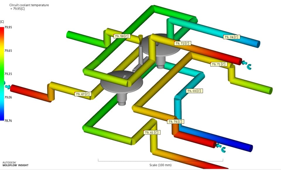
Injection Mold Cooling System
Cooling accounts for up to 70% of the total injection molding cycle time. Poorly designed cooling channels create uneven heat distribution — leading to warpage, sink marks, and dimensional inconsistency. Our cooling circuits are engineered for uniform heat extraction across the entire cavity, minimizing cycle time while maintaining part stability.
- Cooling Channel Diameter: Typically 8–12mm
- Channel Placement: As close to cavity surface as structurally possible
- Coolant: Water-based (standard) · Oil-based (for high-temperature materials)
- Impact: Directly controls cycle time, warpage risk, and dimensional accuracy
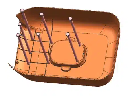
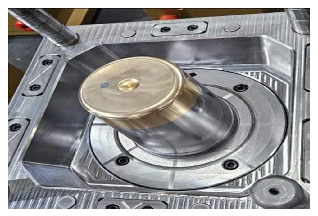
Mold Ejection System
Once the part has cooled and solidified, the ejection system pushes it out of the mold cleanly and without damage. The wrong ejection design leaves visible marks on cosmetic surfaces, causes part distortion, or slows down the automated production cycle. We design the ejection layout around your part geometry and surface finish requirements.
- Air Ejection: For deep-draw or flexible parts
- Lifters: For internal undercuts that pins cannot reach
- Ejector Pins: Most common — simple and reliable for most geometries
- Stripper Plate: Ideal for thin-walled or fragile parts — no visible pin marks
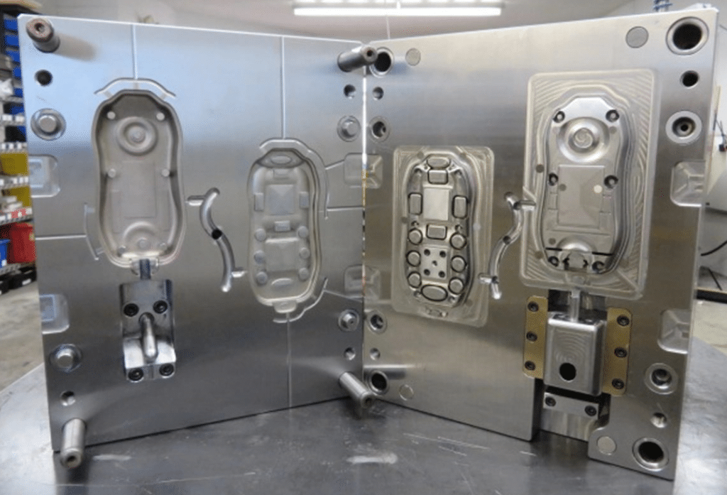
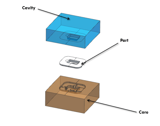
Injection Mold Cavity & Core
The cavity forms the outer surface of your part; the core forms the inner surface. Together they define every dimension, feature, and finish of the final molded part. Steel grade selection, machining precision, and surface treatment at the cavity and core level determine your mold’s accuracy, lifespan, and the surface quality of every part it produces.
- Machining Tolerance: ±0.005mm
- Surface Finish: SPI A0 (mirror) through SPI (matte texture)
- Surface Treatment: Nitriding · Chrome plating · PVD coating — for extended mold life
- Steel Options: P20 · H13 · S136 · NAK80 — selected based on material, volume, and finish requirements
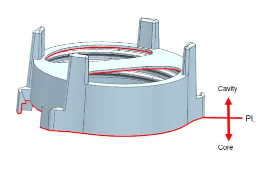
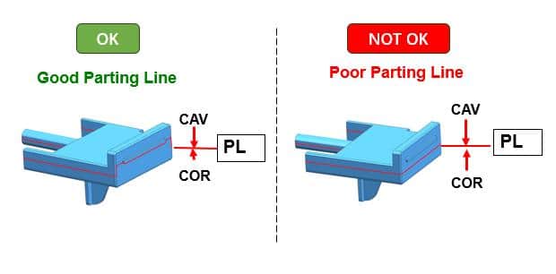
Injection Mold Parting Line & Parting Surface
The parting line is where the two halves of the mold meet. Its position affects where flash appears, how the part is ejected, and whether sealing surfaces or cosmetic faces are compromised. A poorly placed parting line is one of the most common — and most costly — design mistakes in injection mold tooling. We identify and confirm parting line placement during DFM review, not after the mold is built.
- Sealing: Critical for overmolding and insert mold applications
- Position: Agreed and locked during DFM — not after mold completion
- Flash Risk: Minimized through precision mold fit and clamping force calculation
- Cosmetic Impact: Parting line kept away from Class-A surfaces wherever possible
Every one of these systems is engineered and reviewed before we cut steel. Send your part drawing and we’ll walk you through exactly how your custom mold will be built.
DFM Checklist for Mould Plastic Injection
Design for Manufacturability (DFM) is the process of reviewing your part design for injection molding before mold steel is cut — identifying draft angle, wall thickness, gate design, undercut, and parting line issues that would affect part quality, tooling cost, or production efficiency. Here are the six critical checkpoints we review on every project — all at no charge, before any tooling commitment is made.
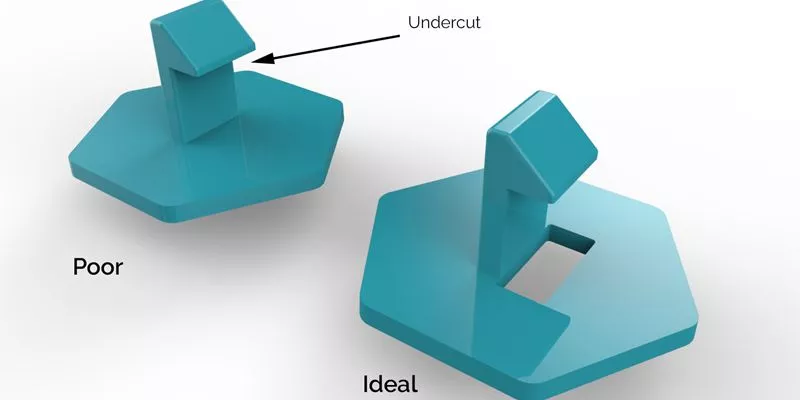
An undercut is any feature that prevents the part from being ejected straight out of the mold — internal threads, side holes, snap clips, and recesses all qualify. Undercuts are not a problem in themselves, but they require additional mold mechanisms that add cost and complexity. Identifying them early keeps your tooling budget on track.
- External Undercuts: Resolved with side-action sliders
- Internal Undercuts: Resolved with lifters or collapsible cores
- Each undercut mechanism adds tooling cost — redesign where function allows
- Thread features: Consider self-tapping screws or post-mold inserts to eliminate internal threads where possible
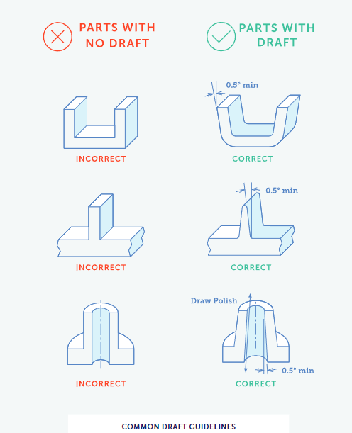
Draft angle is the taper applied to vertical walls so the part releases cleanly from the mold without drag marks or surface damage. Insufficient draft is one of the most common — and most overlooked — causes of ejection problems and cosmetic defects in injection molded parts.
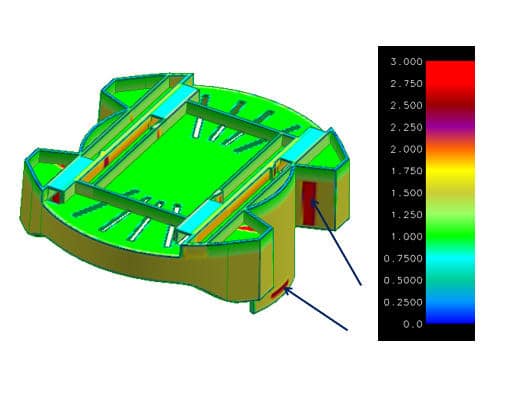
- Recommended Range: 1.2–3.0mm for most roundness.
- Variation: Keep wall thickness as uniform as possible throughout
- Thick-to-Thin Transitions: Use gradual tapers — avoid abrupt section changes
- Material-Specific: PP / PE tolerate thinner walls; PC / Nylon require more careful control
Uniform wall thickness is fundamental to a well-molded part. Thick sections cool slower than thin ones — creating internal stress, sink marks on the surface, and warpage across the part. Uneven wall thickness is one of the leading causes of defects that no process adjustment can fully eliminate after the mold is built.
- Minimum Draft: 0.1° for smooth surfaces
- Textured Surfaces: 2–3° minimum (deeper texture requires more draft)
- Deep Ribs: Add 0.5–1° per 25mm of depth
- Zero-draft walls are possible but require special tooling — adds cost and complexity
The gate is where molten plastic enters the mold cavity. Its position determines where weld lines form, how stress is distributed across the part, whether sink marks appear on visible surfaces, and how evenly the cavity fills. Gate location is one of the highest-impact decisions in mold design — and one of the most expensive to change after the mold is built.
- Place gates away from Class-A (cosmetic) surfaces wherever possible
- Position to achieve balanced fill — avoid hesitation marks and short shots
- Weld line location: Identify early and move away from structural stress zones
- Gate type matched to part geometry: Edge · Submarine · Pin · Hot tip
The parting line is where the two halves of the mold meet — and where a visible line will always appear on the molded part. Its position affects cosmetic appearance, flash risk, sealing performance, and ejection direction. Parting line placement must be confirmed before mold design begins — moving it after steel is cut is expensive and sometimes impossible.
- Keep parting line off Class-A surfaces and sealing faces
- Natural parting: Follow the largest cross-section of the part
- Flash control: Precision mold fit + correct clamping force calculation
- Confirm and lock parting line during DFM — not during T1 trial
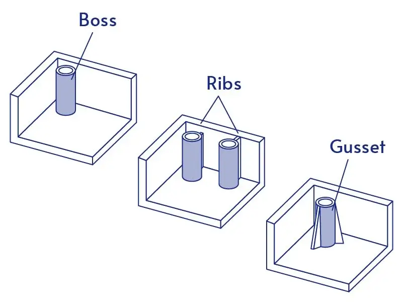
Ribs and bosses add structural strength and mounting features without increasing overall wall thickness — but poorly proportioned ribs are one of the leading causes of sink marks on opposite surfaces. We check every rib and boss geometry against material-specific shrinkage rates and flag adjustments before the mold is designed.
- Rib Thickness: ≤ 60% of adjoining wall thickness to prevent sink marks
- Rib Height: ≤ 3× the rib thickness
- Boss Wall: ≤ 60% of adjoining wall thickness
- Internal Radius: Minimum 0.5mm at all rib-to-wall intersections
Every One of These Checkpoints Is Reviewed — Free — Before We Cut Any Steel
Most tooling problems are design problems that weren’t caught early enough. Our DFM review covers all six checkpoints above and delivers a written report within 24–48 hours — with specific recommendations, not just a list of issues. No tooling commitment required. No cost. Just answers.
Plastic Injection Mold Material Selection Guide
Not all tool steel for injection molds is equal. The right injection mold steel grade depends on your plastic material, required surface finish, expected production volume, and budget. Use the comparison below to identify the best option for your mold.
| P20 | H13 | S136 | NAK80 | Aluminum 7075 | |
|---|---|---|---|---|---|
| Hardness | 28–32 HRC | 48–52 HRC | 48–52 HRC | 38–42 HRC | 150 HB |
| Corrosion Resistance | Low | Low | Excellent | Good | Moderate |
| Mold Life | 300K+ shots | 500K–1M+ shots | 500K–1M+ shots | 300K–500K shots | 5K–10K shots |
| Surface Finish | Up to SPI A2 | Up to SPI A1 | Up to SPI A0 (mirror) | Up to SPI A1 | Up to SPI B2 |
| Best For Plastics | ABS · PP · PE | PC · Nylon · POM | PVC · POM · Transparent resins | ABS · PC · High-gloss parts | Prototype · Low-volume |
| Typical Application | General production tooling | High-volume hard tooling | Corrosive or transparent materials | High-gloss cosmetic parts | Rapid prototype tooling |
| Relative Cost | $ | $$ | $$$ | $$$ | $ |
Not sure which surface finish grade or treatment is right for your part?
Share your part requirements and we’ll specify the optimal finish — matched to your steel grade, plastic material, and cosmetic requirements.
Molding Tooling Surface Finish Options — SPI Standards
Surface finish is specified using the SPI (Society of the Plastics Industry) grading system — the international standard used by mold makers and buyers worldwide. The finish grade you specify directly affects mold machining time, tooling cost, and the final appearance of every molded part.
| Grade | Level | Ra | Recommended Steel | Best For | Cost |
|---|---|---|---|---|---|
| A1 | Mirror — Diamond Buff | ≤ 0.012μm | S136 | Optical lenses · Transparent parts | $$$$ |
| A2 | Mirror — High Gloss | ≤ 0.025μm | S136 / H13 | Medical devices · High-end consumer products | $$$$ |
| A3 | Mirror — Standard | ≤ 0.05μm | H13 / NAK80 | Consumer electronics · Premium housings | $$$ |
| B1 | Semi-Gloss — Fine | ≤ 0.05μm | H13 / NAK80 | Automotive interiors · Electronic shells | $$$ |
| B2 | Semi-Gloss — Medium | ≤ 0.1μm | H13 / P20 | Consumer product shells · Appliance parts | $$ |
| B3 | Semi-Gloss — Coarse | ≤ 0.15μm | P20 | General visible surfaces | $$ |
| C1 | Matte — Fine | ≤ 0.35μm | P20 / H13 | Industrial parts · Internal mechanisms | $ |
| C2 | Matte — Medium | ≤ 0.7μm | P20 | Structural components | $ |
| C3 | Matte — Coarse | ≤ 1.0μm | P20 | Non-cosmetic parts | $ |
| D1 | Texture — Glass Bead Blast | — | P20 / H13 | Grip surfaces · Non-cosmetic parts | $ |
| D2 | Texture — #240 Oxide Blast | — | P20 | Prototype validation · Rough texture | $ |
| D3 | Texture — #24 Oxide Blast | — | P20 | Heavy texture · Industrial surfaces | $ |
Not sure which injection mold surface finish grade or mold surface treatment is right for your part? Share your part requirements and we’ll specify the optimal finish — matched to your steel grade, plastic material, and cosmetic requirements.
Plastic Material & Precision Injection Mold Compatibility Guide
The plastic material you choose directly determines which mold steel, surface finish, gate design, and cooling strategy your injection mold requires. Use this guide to match your material to the right mold configuration — before your tooling is designed.
| Material | Common Applications | Recommended Steel | Surface Finish | Shrinkage Rate | Gate Type | Key Notes |
|---|---|---|---|---|---|---|
| ABS | Consumer electronics · Automotive interiors · Appliance housings | P20 / NAK80 | SPI B1–B2 | 0.4–0.5% | Edge · Submarine | Good flow · Susceptible to sink marks if wall thickness is uneven |
| PP | Packaging · Medical containers · Automotive parts | P20 / H13 | SPI B2–C1 | 1.6–1.8% | Edge · Hot tip | High shrinkage — careful mold compensation required · Warps easily |
| PC | Optical lenses · Transparent housings · Medical devices | H13 / S136 | SPI A1–A2 | 0.5–0.6% | Direct · Hot tip (larger gate) | Poor flow — higher injection pressure needed · Must be dried before molding |
| Nylon PA6/PA66 | Automotive under-hood · Gears · Structural brackets | H13 | SPI B2–C1 | 1.2–1.6% | Edge · Submarine | Moisture-absorbent — must be dried · Glass-filled grades accelerate mold wear |
| POM / Acetal | Precision gears · Bearings · Fuel system parts | S136 (corrosion-resistant essential) | SPI B1–B2 | 1.8–2.0% | Edge (short gate) | Releases formaldehyde gas — corrosive to standard steels · S136 required |
| TPU | Flexible connectors · Phone cases · Seals | NAK80 / H13 | SPI B2–D1 | 0.5–2.0% | Hot tip preferred | Soft at ejection — strengthened ejection system required · Moisture-sensitive |
| TPE | Overmolded grips · Soft-touch surfaces · Medical seals | NAK80 / P20 | SPI C1–D2 | 0.5–2.0% | Hot tip · Submarine | Most common in overmolding over ABS/PP · Confirm substrate compatibility first |
Not sure which mold configuration is right for your plastic material?
Tell us your material grade and part geometry — our engineers will recommend the optimal steel, finish, gate design, and cooling strategy for your injection mold, free of charge.
What Affects Injection Molding Mold Cost?
Injection mold pricing is not arbitrary — every cost driver is traceable to a specific design decision, material choice, or production requirement. Understanding these five factors before you request a quote helps you make better tooling decisions and get more accurate pricing from day one.
FACTOR 01
Part Complexity
The more complex your part geometry, the more complex — and more expensive — the injection mold required to produce it. Undercuts require sliders or lifters. Internal threads require collapsible cores. Thin walls require precision machining and tighter process control. Every additional feature that complicates ejection, filling, or cooling adds engineering time, machining time, and mold trial time.
🔵⚪⚪⚪Simple geometry — minimal features
🔵🔵⚪⚪Moderate — some undercuts, standard ribs
🔵🔵🔵🔵High — multiple undercuts, threads, thin walls
FACTOR 02
Number of Cavities
Cavity count is one of the most direct levers you have over both tooling cost and per-part cost — and the two move in opposite directions. A single-cavity mold costs less to build but produces one part per cycle. A four-cavity mold costs more to build but produces four parts per cycle at roughly the same machine time — reducing your per-part cost by up to 60–70%. The right cavity count depends entirely on your annual volume.
🔵⚪⚪⚪1-cavity — lowest tooling, highest per-part
🔵🔵🔵⚪2–4 cavity — balanced investment
🔵🔵🔵🔵8–16+ cavity — highest tooling, lowest per-part
FACTOR 03
Mold Steel Grade
The steel grade you choose determines how long your mold lasts, what surface finish it can hold, and how much it costs to machine. There is no “best” steel — only the right steel for your specific requirements. Aluminum tooling is fast and inexpensive but limited to low volumes. H13 and S136 are specified for high-volume, high-precision applications at a higher upfront cost that pays back over millions of cycles.
🔵⚪⚪⚪ Aluminum — lowest cost, up to 10K shots
🔵🔵🔵⚪ P20 — mid-range, up to 500K shots
🔵🔵🔵🔵 H13 / S136 — highest, 500K–1M+ shots
FACTOR 04
Expected Production Volume
Your expected annual production volume is the single most important input when specifying an injection mold — because it determines everything else. Volume drives cavity count, steel grade, cooling design, runner system choice, and mold life requirement. Getting the volume estimate wrong at the tooling stage is one of the most common — and most costly — mistakes in new product development.
🔵⚪⚪⚪<5K/yr — prototype or bridge tooling
🔵🔵🔵⚪5K–50K/yr — bridge or light production
🔵🔵🔵🔵500K+/yr — hardened multi-cavity tooling
Ready to get an accurate injection mold quote?
Upload your part drawing and tell us your expected annual volume. We’ll assess all five cost factors and respond with a detailed, transparent quote within 24 hours — no hidden fees, no surprise charges.
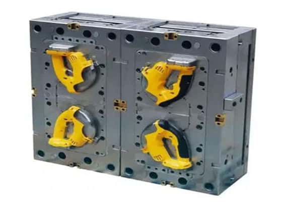
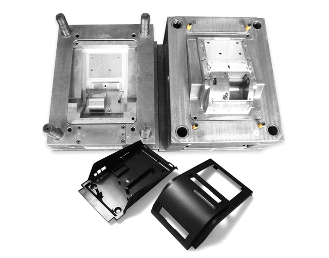
Molds For Plastic Projects
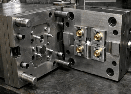
Industrial Connector Insert Mold
Insert Molding
2-Cavity
Hot Runner
- UK
- View project details
Industrial Connector Insert Mold
Insert Molding
2-Cavity
Hot Runner
- UK
- View project details
Industrial Connector Insert Mold
Insert Molding
2-Cavity
Hot Runner
- UK
- View project details
Working on a similar project?
Send your drawing and we’ll recommend the right tooling approach based on your material, volume, and timeline.
Injection Mold Frequently Asked Questions
Everything you need to know before starting your injection mold project — answered by our engineering team.
Ready to Start Your Injection Molding Tooling Project?
Send your part drawing and tell us your requirements. Our injection mold engineers will review your design, run a full DFM analysis, and respond with a detailed, transparent quote within 24 hours — no hidden fees, no obligations.
Accepted file formats: STEP · IGES · STP · DWG · PDF · DXF. Response within 24 hours · English-speaking engineering team · Dongguan, China
Injection Mould · Die Casting Die · Stamping Die · Silicone Mould · Vacuum Casting · Thermosetting Mould