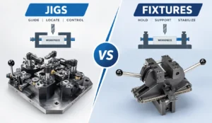


Understanding the difference between jigs and fixtures helps engineers choose the right tooling for drilling, milling, CNC machining, assembly, inspection, and repetitive manufacturing. The right design can reduce setup time, minimize positioning errors, improve repeatability, and support more reliable production.
This guide explains how jigs and fixtures work, compares their key differences, and outlines the design considerations that matter when developing custom tooling for a specific part or manufacturing process.
Jigs vs. Fixtures: The Quick Answer
A jig locates and supports a workpiece while also guiding a tool, commonly through a drill bushing during drilling operations. A fixture locates, supports, and clamps a workpiece in a repeatable position but generally does not guide the cutting tool.
Choose a jig when tool guidance is required. Choose a fixture when accurate workpiece positioning, secure holding, and repeatable processing are the main requirements.

What Is a Jig?
A jig is a manufacturing device that holds and locates a workpiece while guiding a tool or operation along a defined path or position. One of its most recognizable features is a tool-guiding element, such as a drill bushing, that helps maintain the intended tool location.
Jigs are commonly used in drilling, reaming, tapping, and similar operations where the location of a hole or feature must remain consistent across multiple parts. Depending on the application, a jig may also incorporate locating pins, clamps, support elements, and replaceable wear components.
How Does a Jig Work?
The workpiece is positioned against designated locating surfaces or pins and secured using an appropriate clamping mechanism. The jig then guides the tool or establishes a controlled operating position, helping reduce dependence on manual marking and operator judgment.
For example, a drilling jig can use hardened drill bushings to guide a drill into a specified position. This helps maintain hole location consistency when multiple parts must be processed using the same setup.
Common Types of Jigs
- Drilling jigs: Guide drills to specified hole locations.
- Template jigs: Use a template to establish feature positions or guide an operation.
- Plate jigs: Use a plate structure to locate and guide tools relative to a workpiece.
- Channel jigs: Support and locate suitable workpieces within a channel-shaped body.
- Box jigs: Enclose or support a workpiece and may allow access to multiple faces, depending on the design.
Tool guidance is a defining feature of many jigs. The required tool clearance, guide-bushing location, wear resistance, chip evacuation, and operator access should all be considered during design.
What Is a Fixture?
A fixture is a device that accurately locates, supports, and holds a workpiece during a manufacturing or inspection operation. Its primary purpose is to establish a stable and repeatable relationship between the workpiece and the machine, tool, or measuring system.
Unlike a typical drilling jig, a fixture generally does not guide the cutting tool. Instead, it provides the locating references and clamping arrangement needed to keep the workpiece in the intended position during processing.
How Does a Fixture Work?
A fixture uses locating surfaces, pins, stops, supports, clamps, or other purpose-designed components to position the workpiece. The arrangement must resist the forces generated by the operation without causing unacceptable movement or distortion.
In CNC milling, for example, a fixture establishes the workpiece datum relative to the machine coordinate system. Properly designed locating and clamping features help the machine process the intended surfaces while maintaining the required dimensional relationships.
Common Types of Fixtures
- Machining fixtures: Hold workpieces during milling, turning-related setups, drilling, or other machining processes.
- Assembly fixtures: Position components during fastening, bonding, joining, or assembly.
- Welding fixtures: Maintain component position and alignment during welding.
- Inspection fixtures: Establish repeatable part positioning for dimensional checks or quality inspection.
- Modular fixtures: Use configurable components to accommodate different workpieces or production requirements.
- Dedicated fixtures: Are designed around a specific part, process, or family of components.

Jigs vs. Fixtures: Key Differences
The main distinction is whether the tooling guides the tool. Both jigs and fixtures can locate, support, and secure a workpiece, but their additional functions and typical applications differ.
| Comparison Factor | Jig | Fixture |
|---|---|---|
| Primary function | Locates the workpiece and guides the tool or operation. | Locates, supports, and holds the workpiece. |
| Tool guidance | Typically includes a tool-guiding feature, such as a drill bushing. | Generally does not guide the cutting tool. |
| Workpiece positioning | Uses locating features to establish the required position. | Uses locating features and supports to establish a stable position. |
| Typical applications | Drilling, reaming, tapping, and guided operations. | CNC machining, milling, assembly, welding, and inspection. |
| Common components | Guide bushings, locating pins, clamps, and a jig body. | Locators, supports, stops, clamps, base plates, and workholding elements. |
| Accuracy considerations | Tool-guide accuracy, workpiece location, clearance, and wear. | Datum location, clamping stability, rigidity, and machine alignment. |
| Design priority | Consistent tool positioning and workpiece location. | Repeatable positioning and resistance to process forces. |
| Customization | Depends on the workpiece, tool path, and guided operation. | Depends on part geometry, machine interface, access, and process loads. |
On mobile devices, swipe horizontally to view the complete comparison table.
The terms are not always mutually exclusive in practical manufacturing. Some tooling combines workpiece locating and clamping with tool-guiding features. The most useful distinction is the function the tooling is designed to perform.
How Jigs and Fixtures Locate and Hold Workpieces
Accurate tooling design requires more than simply clamping a part in place. Engineers must define how the workpiece is located, how movement is constrained, and how process forces are transferred through the tooling.
Workpiece Location and the 3-2-1 Principle
The 3-2-1 locating principle is a common method for explaining how a workpiece can be positioned using six independent locating contacts. In a conventional arrangement, three contacts establish a primary datum plane, two establish a secondary datum, and one establishes a tertiary datum.
This arrangement helps constrain the workpiece's six rigid-body degrees of freedom: three translational and three rotational. The exact locating scheme must be adapted to the part geometry, datum structure, required access, and manufacturing process.
Locators establish the position of the workpiece; clamps apply force to keep it seated against those locators. Treating these as separate design functions helps reduce unintended movement and positioning variation.
Clamping Force and Workpiece Stability
Clamping must provide enough force to maintain contact with the locating surfaces and resist operational loads. Excessive clamping force, however, can deform thin-walled, flexible, or precision components.
- Position clamps so that their forces support stable contact with the locating features.
- Consider cutting forces, vibration, acceleration, and other loads generated by the process.
- Use suitable support points for parts that may bend or deflect under clamping pressure.
- Provide access for tools, operators, chip removal, and inspection where required.
- Consider wear, maintenance, and repeatable replacement of locating components.
Rigidity and Repeatability
A fixture that appears rigid under static conditions may still experience movement or deformation under actual operating loads. The base, locating elements, supports, clamps, and machine interface all contribute to the overall behavior of the tooling system.
Repeatability also depends on factors beyond the fixture itself, including workpiece variation, locating-surface condition, contamination, clamping sequence, machine condition, and operator technique. These factors should be considered when setting realistic performance requirements.
Repeatable positioning does not automatically guarantee that every manufactured part will meet its dimensional tolerances. Process capability, machine accuracy, tool condition, measurement methods, and workpiece variation must also be evaluated.
Common Applications of Jigs and Fixtures
Jigs and fixtures are used across many manufacturing industries. The correct tooling depends on the operation being performed, the geometry of the part, the production volume, and the required level of consistency.
CNC Machining
Machining fixtures locate and secure components during milling and other machining operations, helping maintain datum relationships and resist cutting forces.
Drilling and Hole Making
Drilling jigs help guide tools to specified hole positions, especially when multiple workpieces require consistent hole patterns.
Assembly and Joining
Assembly fixtures position components during fastening, bonding, welding, or joining to help maintain alignment throughout the operation.
Inspection and Quality Control
Inspection fixtures establish repeatable part positioning for dimensional verification, comparison against datums, and selected quality checks.

How to Choose Between a Jig and a Fixture
The decision should start with the manufacturing operation rather than the name of the tool. Consider the following questions before selecting or designing custom tooling.
Does the operation require tool guidance?
If the tooling must guide a drill or another tool to a defined location, a jig may be appropriate. If the machine or process already controls the tool path, a fixture may be sufficient.
What positioning accuracy is required?
Identify the relevant datums, dimensional tolerances, feature relationships, and inspection requirements. These determine the locating strategy and the accuracy needed from the tooling.
What forces will the tooling experience?
Machining, welding, assembly, and other operations create different loads. Evaluate stiffness, clamping force, support locations, and potential workpiece deformation.
How many parts will be processed?
Production volume affects whether dedicated, modular, or adjustable tooling is appropriate. Higher volumes may justify investment in tooling that reduces setup time and improves consistency.
Can the workpiece be loaded and removed efficiently?
Consider operator access, loading direction, clamping sequence, chip evacuation, cleaning, and the possibility of incorrect loading. Practical usability is an important part of tooling performance.
How will the tooling be verified and maintained?
Define how critical locating features, guide elements, interfaces, and wear components will be inspected. Establishing a maintenance approach helps preserve performance over repeated production cycles.
Key Considerations in Custom Jig and Fixture Design
Custom tooling should be developed around the actual workpiece and process. A design that works well for one part may not be suitable for another, even when the components appear similar.
Part Geometry and Datum References
The design should account for the part's geometry, functional surfaces, datum references, tolerance requirements, and any features that must remain accessible during processing. The locating scheme should support the required dimensions without unnecessarily over-constraining the workpiece.
Material and Component Selection
Material selection depends on the required stiffness, weight, wear resistance, corrosion resistance, operating environment, and expected production volume. Replaceable bushings, hardened locating pins, and serviceable wear elements may be useful where repeated contact or abrasion is expected.
Manufacturing and Assembly
A practical design should consider how the tooling will be machined, assembled, aligned, and inspected. Accessible fasteners, manageable component sizes, appropriate tolerances, and straightforward maintenance can help reduce manufacturing and lifecycle costs.
Verification and Inspection
Before production use, verify the tooling's critical dimensions and interfaces against the design requirements. Depending on the application, this may include dimensional inspection, setup verification, trial processing, and evaluation of actual workpiece results.
The best tooling design balances positioning accuracy, structural stability, accessibility, ease of use, maintenance, and total cost. Increasing complexity does not necessarily improve the final manufacturing result.
Need a Custom Jig or Fixture for Your Part?
SENSES MOLD supports custom manufacturing projects that require tooling designed around specific part geometries, locating requirements, and production processes. Sharing your CAD files, drawings, tolerances, and intended application helps establish the right tooling approach.
Explore our custom jigs and fixtures solution to learn more about tooling design and manufacturing support.
Frequently Asked Questions About Jigs and Fixtures
What is the main difference between a jig and a fixture?
A jig locates the workpiece and guides the tool or operation, while a fixture locates, supports, and holds the workpiece without typically guiding the cutting tool. Both can improve positioning consistency and production efficiency.
Is a jig more accurate than a fixture?
Not necessarily. Accuracy depends on the tooling design, manufacturing quality, locating strategy, tool or machine capability, workpiece variation, and measurement method. A well-designed fixture can provide highly repeatable positioning, just as a well-designed jig can guide an operation accurately.
Can a fixture be used for CNC machining?
Yes. Fixtures are widely used in CNC machining to establish workpiece position, provide support, and resist cutting forces. They can be designed for specific parts, machining operations, or families of components.
Are jigs only used for drilling?
No. Drilling jigs are a common example because they guide drills to specified locations, but jig designs can support other guided operations depending on the tooling arrangement and process requirements.
What is the 3-2-1 principle in fixture design?
The 3-2-1 principle is a locating approach that uses three contacts for a primary datum plane, two for a secondary datum, and one for a tertiary datum. In a conventional arrangement, it helps constrain the six rigid-body degrees of freedom of a workpiece.
What information is needed to design a custom jig or fixture?
Useful information includes 2D drawings, 3D CAD models, material specifications, critical dimensions and tolerances, the intended manufacturing process, machine or equipment interfaces, production volume, and any loading, access, or inspection requirements.
Should I choose dedicated or modular tooling?
Dedicated tooling is often suitable for stable, repeatable production of a specific part or part family. Modular tooling may be preferable when flexibility, frequent changeovers, or a variety of workpieces are important. The right choice depends on production demand, setup time, accuracy, and lifecycle cost.
Technical References and Further Reading
The following standards, engineering resources, and research publications provide additional information relevant to fixture design, locating principles, and workpiece clamping.
- ASME — Dimensioning and Tolerancing Principles for Gages and Fixtures. Official standard information. This standard addresses specific gage and fixture design practices, including maximum-material-condition size envelopes and virtual-condition boundaries; it is not a universal standard for every production fixture.
- Central Oregon Community College — Manufacturing Jigs and Fixtures (MFG 254). Course outline. Educational coverage of jig and fixture design, clamps, locators, degrees of freedom, and the 3-2-1 principle.
- CIRP Annals — Fixtures and Workpiece Clamping Systems in Machining (2025). Research publication. A review concerning machining fixtures and workpiece clamping systems.
Conclusion: Choosing the Right Tooling for Your Manufacturing Process
The difference between jigs and fixtures comes down to their primary functions. Jigs typically guide a tool while locating the workpiece; fixtures primarily locate, support, and hold the workpiece during processing.
Selecting the right solution requires a clear understanding of the operation, workpiece geometry, datum structure, accuracy requirements, production volume, and operating forces. Thoughtful tooling design can improve setup consistency, simplify production, and support more reliable manufacturing outcomes.
Choose a jig when controlled tool guidance is required. Choose a fixture when repeatable workpiece positioning and secure holding are the main priorities. For more complex operations, a custom tooling design may combine features of both.
Looking for Custom Jig and Fixture Manufacturing?
Have a part drawing, CAD model, or specific production challenge? Discuss your requirements with SENSES MOLD to explore a tooling solution tailored to your application.
Discuss Your Tooling Requirements