
Custom Metal Injection Molding for Precision Metal Parts
SENSES MOLD provides custom Metal Injection Molding (MIM) for small, complex metal components that require repeatable dimensions, fine features, and efficient mass production. From DFM review and MIM tooling to molding, debinding, sintering, secondary machining, and final inspection, we support your project from the initial CAD file through production.
- ≥98% — First-Pass Production Yield
- 15–25 Days — Typical Tooling Lead Time
- ±0.05 mm — Typical Dimensional Tolerance
- Factory-Direct — No Trading Company Markups
- No MOQ Requirement — Flexible Order Quantities
20+ Years | ISO9001 | IATF16949 | Prototype to Production | NDA Available


What Is Injection Molding Metal
Metal Injection Molding (MIM) is a precision manufacturing process that combines fine metal powders with a polymer binder to produce complex metal components through injection molding, debinding, and sintering.
Unlike conventional machining, MIM manufacturing can form complex geometries and multiple features in a single molded part, making it suitable for small, intricate components produced in medium to high volumes.
- Complex Geometries - Fine features and integrated details
- Small Precision Parts - Suitable for compact metal components
- High-Volume Production - Injection molding enables repeatable production of complex MIM parts once tooling and process parameters are validated.
- Near-Net-Shape Manufacturing - Reduce extensive machining by forming much of the final geometry directly during molding and sintering.
Have a Part You’re Considering for MIM?
Send us your 3D CAD file or drawing. Our engineers can review your part and assess MIM feasibility, material options, tooling considerations, and the proposed manufacturing route before tooling begins.
Why Choose Injection Metal Molding?
When MIM Creates a Real Manufacturing Advantage
The value of Metal Injection Molding is not simply its ability to form metal parts. It becomes especially attractive when part complexity, production volume, feature integration, and machining requirements create challenges for conventional manufacturing. At SENSES MOLD, we evaluate MIM from the perspective of the finished component, tooling requirements, production volume, and manufacturing route—not just whether the geometry can be molded.
| Where MIM Creates the Most Value | |
|---|---|
| Your Part Requirement | MIM Advantage |
| Complex 3D geometry | Mold complex features directly |
| Small metal components | Efficient for compact precision parts |
| Multiple functional features | Combine features into one component |
| Medium to high production volume | Repeatable injection-based production |
| Tight dimensional requirements | Controlled tooling, molding, and sintering |
| Reduced machining requirement | Near-net-shape production |

MIM is most effective when part complexity, precision requirements and production volume justify the tooling and sintering process.
Not sure whether MIM fits your part? Send us your 3D model for a feasibility review.
Our Metal Injection Molding (MIM) Manufacturing Capabilities
At SENSES MOLD, we manufacture custom Metal Injection Molding parts from tooling and feedstock preparation through molding, debinding, sintering, machining, and final inspection. Our capabilities are evaluated around your part geometry, material, tolerance, production volume, and application requirements.
| Capability | Our Manufacturing Range |
|---|---|
| Part Size | Small and precision metal components |
| Part Weight | From lightweight precision parts to application-specific components |
| Typical Tolerance | ±0.3%–±0.5% of dimension* |
| Minimum Wall Thickness | Down to approximately 0.3–0.5 mm* |
| Material Options | Stainless Steel, Alloy Steel, Tool Steel and other qualified MIM materials |
| Production Volume | Prototype evaluation → Low-volume → High-volume production |
| Tooling | In-house MIM mold design, manufacturing and optimization |
| Secondary Operations | CNC machining, grinding, drilling, tapping, polishing, heat treatment, passivation and marking |
| Inspection | Dimensional inspection, optical measurement, CMM, hardness, density and material verification |
* Actual achievable values depend on part geometry, material, dimensions, tolerance location and production requirements. Final capability is confirmed during DFM and feasibility review.
Have a MIM part in development?
Send us your 3D CAD file and drawing for a Metal Injection Molding feasibility review.
Metal Injection Molding Materials
MIM Materials for Precision, Performance & Application Requirements
We offer a broad range of Metal Injection Molding Materials for precision components, from stainless steels and alloy steels to titanium, cobalt, nickel, magnetic and tungsten-based materials.
Material selection is evaluated according to strength, hardness, corrosion resistance, wear resistance, temperature, density, magnetic properties, dimensional requirements and production cost.


Stainless Steel MIM
For corrosion-resistant, durable and precision MIM parts.
- MIM 304
- MIM 316L
- MIM 17-4 PH
- MIM 420
- MIM 430
- MIM 430L
- MIM 440C
Alloy Steel MIM
For high-strength mechanical components, wear-resistant parts and demanding industrial applications.
- MIM 4140
- MIM 4340
- MIM 8620
- MIM 9310
- MIM 52100
Tool Steel MIM
For components requiring high hardness, wear resistance and dimensional stability.
- MIM A2
- MIM D2
- MIM H13
- MIM M2
- MIM M4
- MIM S7
Cobalt-Based MIM
For high-wear, corrosion-resistant and demanding medical or industrial components.
- MIM CoCrMo (ASTM F75)
- MIM CoCrW
- MIM CoNiCrMo
- MIM MP35N
- MIM Stellite 6
- MIM Haynes 25
Nickel-Based & Superalloy MIM
For high-temperature, corrosion-resistant and high-performance applications.
- MIM Ni18Co9Mo5
- MIM Inconel 600
- MIM Inconel 625
- MIM Inconel 713LC
- MIM Inconel 738
- MIM Haynes 188
Titanium MIM
For lightweight, high-strength and corrosion-resistant precision components.
- MIM Ti-3Al-2.5V (Grade 9)
- MIM Ti-5Al-2.5Fe (Grade 38)
- MIM Ti-6Al-4V (Grade 5)
- MIM Ti-6Al-7Nb (Grade 26)
- MIM Ti-10V-2Fe-3Al (Grade 20)
- MIM Ti-15Mo-5Zr-3Al (Grade 21)
- MIM Ti-15V-3Cr-3Al-3Sn
Magnetic & Soft Magnetic MIM
For magnetic circuits, electromagnetic components and specialized electronic applications.
- MIM Fe-3Si
- MIM Fe-50Ni ·
- MIM Fe-50Co
Tungsten & Heavy Metal MIM
For high-density, thermal, radiation-shielding and specialized industrial applications.
- MIM W-Cu
- MIM W-Fe
- MIM W-Ni-Co
- MIM W-Ni-Cu
- MIM W-Ni-Fe
Not sure which material is suitable for your product?
Have a specified material but don’t know whether it is suitable for MIM?
Comparing several grades and unsure which one offers the right balance for your application?
Send us your 3D model, drawing or existing material specification. Our engineers can review your requirements and recommend suitable MIM material options before tooling begins.
MIM Part Design & DFM Engineering
Design for Reliable MIM Production Before Tooling
A part that looks manufacturable in CAD may still create problems during Metal Injection Molding. Small changes to geometry can affect mold filling, part release, debinding, sintering and final dimensional consistency. Our engineering team reviews your design before tooling to identify potential MIM manufacturing risks and recommend practical changes where needed.
| Key MIM Design Considerations | |
|---|---|
| Design Area | What We Review |
| Wall Thickness | Uniformity, transitions and areas prone to defects |
| Draft Angle | Reliable mold release without damaging the green part |
| Ribs & Bosses | Feature size, placement and molding stability |
| Holes & Threads | Size, location and post-molding requirements |
| Undercuts | Feasibility and required mold mechanisms |
| Sharp Corners | Stress concentration and material flow risks |
| Parting Line | Positioning to reduce flash and simplify tooling |
| Gate Location | Filling behavior, weld lines and cosmetic requirements |
| Ejection | Ejector placement and green-part strength |
| Complex Features | Feasibility of molding fine and integrated geometries |
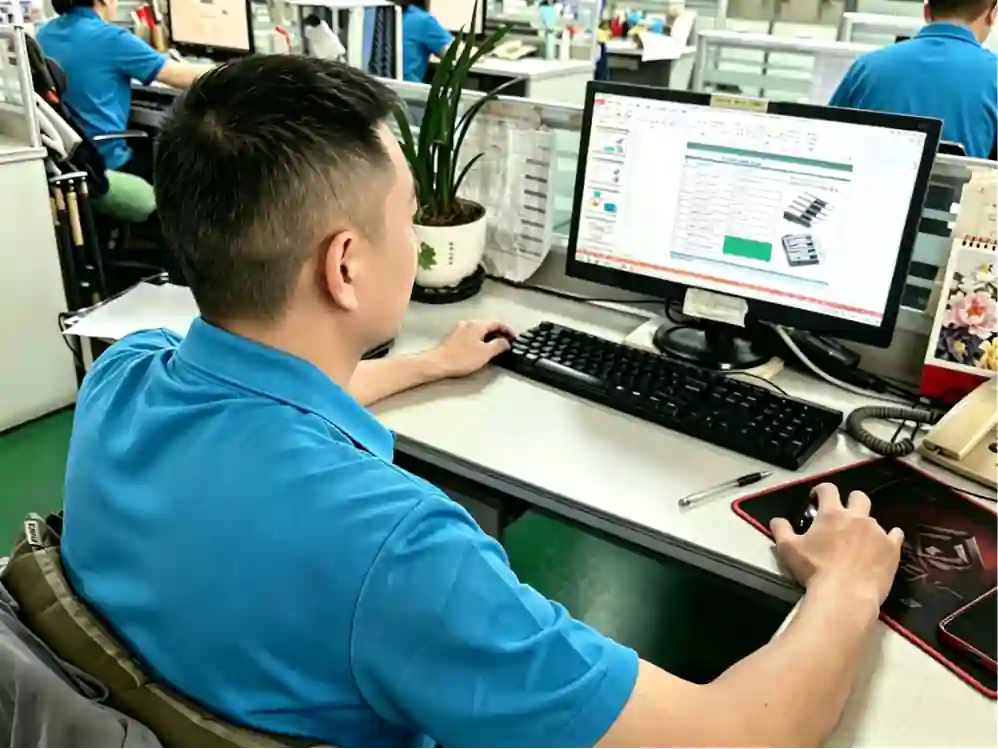
Before You Build the Mold, We can review your 3D CAD Model → Part Geometry → MIM Feasibility → DFM Recommendations → Tooling Direction
This helps identify potential design issues before mold manufacturing, rather than discovering them after the tool is already built.
Is Your Part Design Ready for MIM?
Not sure whether your current design can be molded successfully?
Worried about discovering design problems after the mold is built?
Need to know what should be changed before investing in tooling?
Send your 3D model or drawing. Our engineers review the design for MIM feasibility and DFM risks before tooling starts.
MIM Tooling & Mold Design
In-House MIM Tooling Built Around Your Part Requirements
MIM tooling requires more than simply copying a conventional injection mold. Mold construction must account for complex part geometry, feedstock flow, ejection, debinding, sintering and dimensional change. Our tooling engineers work from your approved part design to develop the mold structure and manufacturing strategy before production begins.

From Tool Design to Production.
DFM Review → Mold Design → Tool Manufacturing → Mold Assembly → Trial Molding → Optimization → Production
Because tooling and MIM manufacturing are managed together, engineering feedback can be addressed before problems move into production.
| MIM Mold Engineering | |
|---|---|
| Tooling Area | Engineering Focus |
| Mold Structure | Cavity, core and overall mold construction |
| Cavity Layout | Cavity arrangement based on part geometry and production volume |
| Gate & Runner | Controlled feedstock flow and balanced filling |
| Ejection System | Reliable removal of green parts without damage |
| Core & Inserts | Complex internal features and replaceable tooling elements |
| Venting | Air evacuation and filling stability |
| Cooling | Mold temperature control and cycle consistency |
| Shrinkage Compensation | Cavity dimensions adjusted for downstream dimensional change |
Avoid Costly MIM Tooling Changes Before Production
A part that looks suitable for injection molding may still need changes for feedstock flow, debinding, sintering and dimensional control.
Send Your CAD File → Get an Engineer-Led MIM Feasibility Review Before Tooling
Metal Injection Molding Process
From Metal Feedstock to Finished MIM Parts
Metal Injection Molding combines precision injection molding, controlled debinding and sintering to produce complex metal components with repeatable results. At SENSES MOLD, we coordinate the process from tooling and molding through debinding, sintering, secondary operations and final inspection, giving you one factory-direct manufacturing partner from start to finish.
The appropriate metal powder and material grade are selected for the required application.
Why It MattersEstablishes the material foundation for the finished MIM component.
Metal powder is combined with a binder system to create moldable feedstock.
Why It MattersProvides consistent material flow and molding behavior.
Feedstock is injected into the mold to form the required part geometry.
Why It MattersReplicates complex features and creates the green part.
The binder is gradually removed from the molded green part.
Why It MattersPrepares the part for controlled sintering while maintaining its geometry.
The debound part is heated under a controlled atmosphere to develop its final structure.
Why It MattersDevelops the required density, strength and dimensional stability.
Critical features may be CNC machined, ground, drilled or tapped.
Why It MattersAchieves critical dimensions beyond the as-sintered capability.
Parts receive polishing, passivation, marking or other required finishing.
Why It MattersMeets final surface, appearance and application requirements.
Finished parts are measured and tested against drawing and quality requirements.
Why It MattersConfirms dimensional and functional compliance before delivery.
One MIM Process. One Manufacturing Partner.
From feedstock preparation to injection molding, debinding, sintering, secondary operations and final inspection, we coordinate the connected manufacturing process for your MIM parts—reducing supplier coordination and keeping process control under one manufacturing partner.
MIM Shrinkage & Dimensional Control
Metal Injection Molding Shrinkage is an important engineering factor because MIM parts change size during debinding and sintering. Proper MIM shrinkage compensation starts with material selection and mold design, then continues through molding, sintering and final inspection.
At SENSES MOLD, we evaluate MIM dimensional variation across the manufacturing process to help achieve the required MIM tolerance and final part dimensions.
How We Control MIM Dimensional Accuracy
| MIM Dimensional Control Step | What We Control |
|---|---|
| 01 Material Selection | Evaluate material-specific shrinkage behavior before tooling and production. |
| 02 Shrinkage Evaluation | Consider expected dimensional changes during molding, debinding and sintering. |
| 03 Mold Compensation | Adjust mold cavity dimensions to account for expected MIM shrinkage. |
| 04 Injection Molding | Maintain consistent molding conditions to reduce variation in the green part. |
| 05 Debinding Control | Control binder removal to help minimize distortion before sintering. |
| 06 Sintering Control | Control the sintering cycle and atmosphere to support dimensional stability. |
| 07 Dimensional Inspection | Verify critical dimensions after sintering and secondary operations against drawing requirements. |

Worried About MIM Dimensional Problems After Sintering?
Unexpected MIM shrinkage can turn into out-of-tolerance parts, costly rework and delayed delivery.
MIM Secondary Operations & Finishing
What Happens After MIM Sintering?
Sintering produces the primary MIM component, but some parts require MIM secondary operations and finishing to achieve their final functional, dimensional or surface requirements. Depending on the part, MIM CNC machining, grinding, drilling, tapping, polishing, tumbling, heat treatment, passivation, laser marking and assembly can be added after sintering.
At SENSES MOLD, these secondary processes can be coordinated as part of the manufacturing flow, helping customers receive finished MIM components rather than semi-finished sintered parts.

From Sintered Part to Finished Component
Sintering → Machining → Surface Treatment → Marking → Assembly → Finished Part
Not every MIM part requires every operation. The MIM finishing process is selected according to the final drawing, functional requirements, surface specifications and production needs.
MIM Secondary Operations & Finishing Options
| Secondary Operation | What It Adds to the Part |
|---|---|
| MIM CNC Machining | Tight-tolerance features, critical interfaces and precise dimensions |
| MIM Grinding | Precision surfaces and controlled dimensional adjustment |
| MIM Drilling | Additional holes and precise openings |
| MIM Tapping | Internal threads and threaded features |
| MIM Polishing | Smoother surfaces and improved appearance |
| MIM Tumbling | Deburring, edge treatment and surface uniformity |
| MIM Heat Treatment | Required hardness and mechanical properties |
| MIM Passivation | Improved corrosion resistance for stainless steel parts |
| MIM Laser Marking | Part numbers, logos, codes and traceability |
| MIM Assembly | Integration of MIM parts with other components |
Need More Than a Sintered MIM Part?
Managing machining, finishing and assembly through separate suppliers can mean more communication, longer lead times and additional coordination work.
MIM Quality Control & Inspection
How Do We Verify MIM Part Quality?
Once MIM parts are produced, the final question is simple: Do they meet the drawing, material and functional requirements? Our inspection process verifies critical characteristics before parts are released for shipment.
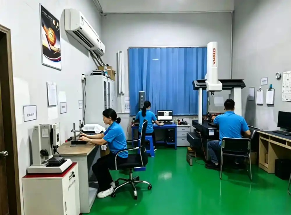
MIM Inspection & Quality Checks
| Inspection Area | What We Verify |
|---|---|
| Material Verification | Material grade and specified material requirements |
| Dimensional Inspection | Critical dimensions and drawing tolerances |
| CMM Measurement | Complex geometries and critical features |
| Optical Measurement | Small features, profiles and fine details |
| Hardness Testing | Required hardness after sintering or heat treatment |
| Density Testing | Sintered density and material consistency |
| Surface Roughness | Required surface condition and finish |
| Visual Inspection | Surface defects, cracks and visible abnormalities |
| Final Inspection | Overall compliance with agreed quality requirements |
Worried Your MIM Parts May Fail Inspection?
Not sure which dimensions need to be controlled?
Concerned about material, hardness, density or surface requirements being missed?
Need to know how your finished MIM parts will be verified before production?
Send us your 2D drawing, 3D model or quality requirements. Our engineers can review the critical characteristics and help define an appropriate inspection approach before production begins.
Metal Injection Molding Defects & Troubleshooting
MIM Defects Need Manufacturing-Level Troubleshooting
MIM defects are not always caused by a single process parameter. Material, tooling, molding, debinding and sintering can all affect the final result. At SENSES MOLD, our engineers review the defect together with the actual manufacturing conditions to identify where the problem originates and determine the appropriate corrective action.

From Defect Detection to Corrective Action
When a problem appears, we don’t treat the finished part in isolation. Our manufacturing team can trace the issue across material → tooling → molding → debinding → sintering → secondary operations, helping determine whether the corrective action should come from the part design, mold, material or production process.
This approach helps reduce repeated trials, unnecessary tooling changes, scrap and production delays.
| MIM Problem | Possible Cause | How We Troubleshoot It |
|---|---|---|
|
Cracking
|
Molding stress, debinding or material behavior | Review part geometry, molding conditions and debinding parameters |
|
Warpage
|
Uneven shrinkage or sintering conditions | Check geometry, part support and sintering parameters |
|
Short Shot
|
Poor filling or unsuitable flow conditions | Review gate design, filling conditions and feedstock behavior |
|
Flash
|
Mold mismatch or excessive molding pressure | Inspect parting surfaces and adjust tooling or molding conditions |
|
Dimensional Variation
|
Material or process variation | Review shrinkage behavior, tooling compensation and process consistency |
|
Distortion
|
Debinding or sintering-related deformation | Identify the deformation stage and adjust the corresponding process |
|
Sintering Defects
|
Furnace conditions or part arrangement | Review sintering temperature, atmosphere and loading conditions |
|
Density Variation
|
Feedstock or process inconsistency | Check material consistency and production parameters |
Facing a MIM Production Problem?Cracking after debinding? Dimensions changing after sintering? Flash, warpage or density variation during production?
Instead of repeatedly adjusting the process without knowing the root cause, let the team involved in manufacturing review the problem with you.
MIM Prototyping to Mass Production
From MIM Feasibility to Stable Mass Production
A successful MIM project needs more than a manufacturable part. The design, tooling, material, process and quality requirements must be validated before moving into repeat production. Instead of handing the project between separate tooling, molding and finishing suppliers, SENSES MOLD can coordinate the key manufacturing stages under one production workflow. This helps reduce communication gaps, repeated engineering reviews and avoidable delays when moving from prototype to production.
| Production Stage | What Happens | Customer Benefit |
|---|---|---|
| 01 Feasibility | Review part geometry, material requirements, tolerances and production volume. | Identify potential MIM risks before tooling investment. |
| 02 Prototype | Validate the part concept, material and critical features. | Confirm the design before committing to full production. |
| 03 Tooling | Develop and manufacture the MIM mold based on the validated design. | Build tooling around actual production requirements. |
| 04 Trial | Run initial molded parts and evaluate the production process. | Identify potential issues before production release. |
| 05 Validation | Verify dimensions, material properties and required quality characteristics. | Confirm the part meets agreed specifications. |
| 06 Mass Production | Move into controlled repeat production with established process parameters. | Achieve consistent parts for ongoing production orders. |
Moving from Prototype to MIM Production?
Not sure if your current design is ready for MIM tooling?
Worried that problems will only appear after the mold is built?
Need a manufacturing partner that can stay with the project through validation and production?
MIM Cost & Production Planning
What Actually Affects MIM Manufacturing Cost?
MIM cost is not determined by material price alone. Part geometry, production volume, tooling design and required post-processing can all change the final manufacturing cost.
MIM Cost Drivers & How to Reduce Manufacturing Cost
| MIM Cost Factor | What Drives Cost | How to Reduce Cost |
|---|---|---|
|
01
Material
|
Material grade and powder consumption | Select the right material grade and avoid unnecessary material requirements |
|
02
Part Complexity
|
Fine features, undercuts and difficult geometries | Simplify non-functional features where possible |
|
03
Part Size
|
Material usage and production requirements | Optimize part geometry and material usage |
|
04
Production Volume
|
Tooling amortization and production efficiency | Select a suitable production volume and cavity strategy |
|
05
Tooling
|
Mold structure, cavity count and tooling complexity | Optimize mold structure and cavity layout |
|
06
Machining
|
CNC machining, grinding, drilling, tapping and other secondary work | Design critical features for the MIM process where possible |
|
07
Finishing
|
Polishing, passivation, heat treatment, marking and other finishing | Specify only the finishing requirements the application actually needs |
|
08
Tolerance
|
Tight tolerances may require additional process control or machining | Apply tight tolerances only to critical dimensions |
|
09
Quality Requirements
|
Inspection, testing and documentation requirements | Match inspection requirements to actual product risks |
Trying to Hit a Target MIM Part Cost?
Not sure why your current design is expensive to manufacture?
Want to reduce tooling or secondary machining costs before production?
Send your 3D CAD + 2D Drawing + Annual Volume + Target Cost.
MIM Applications & Industries
Metal Injection Molding for Precision Industries
SENSES MOLD supports custom MIM production for small, complex metal components across automotive, medical, electronics, consumer, and industrial applications. Our engineering team supports projects from DFM review and material selection through tooling, MIM production, debinding, sintering, and final inspection.

Automotive
Connectors · Sensor Components · Brackets
Tight tolerances · Complex geometries · Repeatable production
Medical
Surgical Components · Instrument Parts · Precision Housings
Corrosion resistance · Dimensional control · Consistent quality
Electronics
Connectors · Terminals · Shielding Parts
Fine features · Dimensional stability · High-volume production
Consumer Products
Hinges · Locks · Wearable Components
Complex shapes · Surface quality · Production consistency
Industrial Equipment
Valves · Gears · Actuators
Strength · Wear resistance · Dimensional stability
Precision Hardware
Tool Components · Fasteners · Small Mechanisms
Hardness · Complex features · Repeatable productionYour Industry Is Only the Starting Point.
Have a metal component with complex geometry or demanding production requirements? Let’s explore whether MIM is the right fit for your part.
Why Choose SENSES MOLD for Metal Injection Molding?
Choosing a MIM supplier is not only about producing metal parts. Tooling, engineering decisions, process control and communication all affect the final result. SENSES MOLD provides a factory-direct manufacturing solution from engineering review and tooling to production and secondary operations.
Factory-Direct Manufacturing
Work directly with the manufacturing team instead of coordinating multiple suppliers. This keeps engineering communication, tooling and production aligned throughout the project.
In-House Tooling
Our tooling team handles mold design and manufacturing in-house, allowing tooling decisions to be closely coordinated with part geometry and production requirements.
Engineering Support
Our engineers review your CAD files and drawings to identify potential manufacturing issues early and provide practical recommendations before tooling begins.
From Prototype to Production
MIM projects often require adjustments between initial trials and production release. We support the project through tooling, validation and repeat production.
Secondary Manufacturing
CNC machining, grinding, drilling, tapping, polishing, passivation, laser marking and assembly can be coordinated as part of the finished-part manufacturing process.
Quality-Focused Production
Quality control is integrated throughout the manufacturing process, with dimensional inspection and material verification used to confirm parts against project requirements.
Delivered for Global OEM Customers
Injection Molding Machine Capacity
Quality Management
Precision Molding Capability
Tooling & Plastic Manufacturing Experience
Looking for a MIM Manufacturing Partner?
Tell us what you’re trying to manufacture. Our engineering team can review your requirements and discuss the most practical way forward.
Metal Injection Molding Engineering Insights
Practical Experience Sharing From Design to Production
With years of experience in insert molding manufacturing, our engineering team shares practical insights on part design, material selection, insert selection, tooling considerations, and production optimization.These engineering resources are based on real manufacturing experience and help product developers reduce potential risks before moving into tooling and mass production.
- MIM Process Comparisons
MIM vs CNC Machining: When Should You Switch to MIM?
MIM vs Die Casting: Which Is Better for Small Complex Metal Parts?
MIM vs Metal 3D Printing: Prototype or Production?
MIM vs Investment Casting: Which Process Fits Small Complex Parts?
- MIM Part Design & Cost Optimization
How to Design a Metal Part for Cost-Effective MIM Production
How to Reduce CNC Machining After MIM
When Should an Existing Metal Part Be Redesigned for MIM?
How Part Consolidation Can Reduce MIM Assembly Costs
- Choosing a MIM Manufacturer
How to Choose a Metal Injection Molding Manufacturer
Top Questions to Ask a MIM Manufacturer Before RFQ
How to Compare MIM Supplier Quotes
How to Qualify a MIM Supplier for Mass Production
- MIM Production Decision Guides
Top Factors That Can Delay a MIM Project
Top Reasons MIM Projects Require Tooling Changes
Top Challenges When Scaling MIM From Trial to Mass Production
Top Factors That Affect MIM Production Repeatability
Related Manufacturing Services
Related Manufacturing Services for Complete Metal Part Production
MIM is often part of a larger manufacturing program. Depending on the part requirements, tooling strategy, and final assembly needs, additional manufacturing processes may be required before or after MIM production.
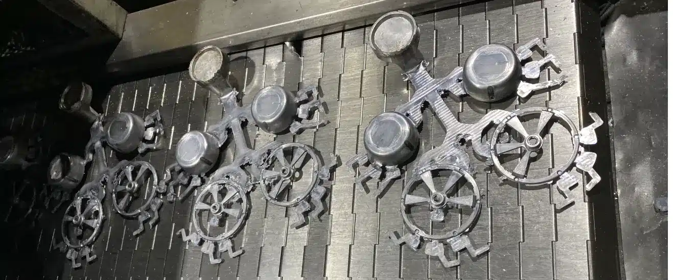
Die Casting
Die casting provides an efficient option for selected aluminum and zinc components where part size, geometry, and production requirements favor a casting process.
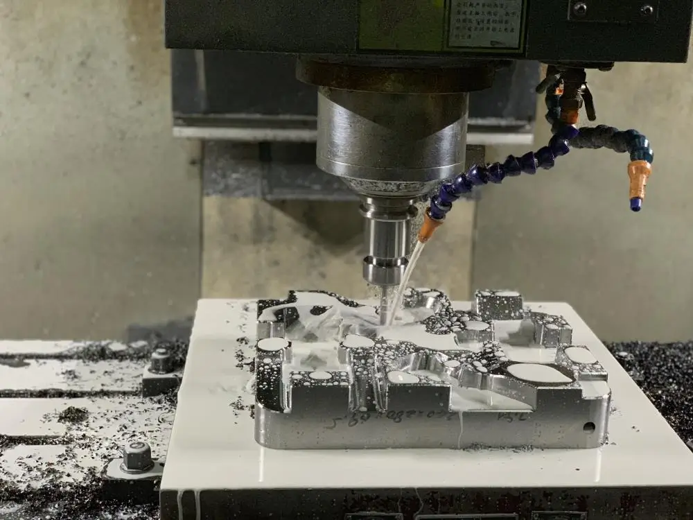
CNC Machining
CNC machining can support MIM projects when specific dimensions, interfaces, holes, threads, or functional surfaces require additional machining.
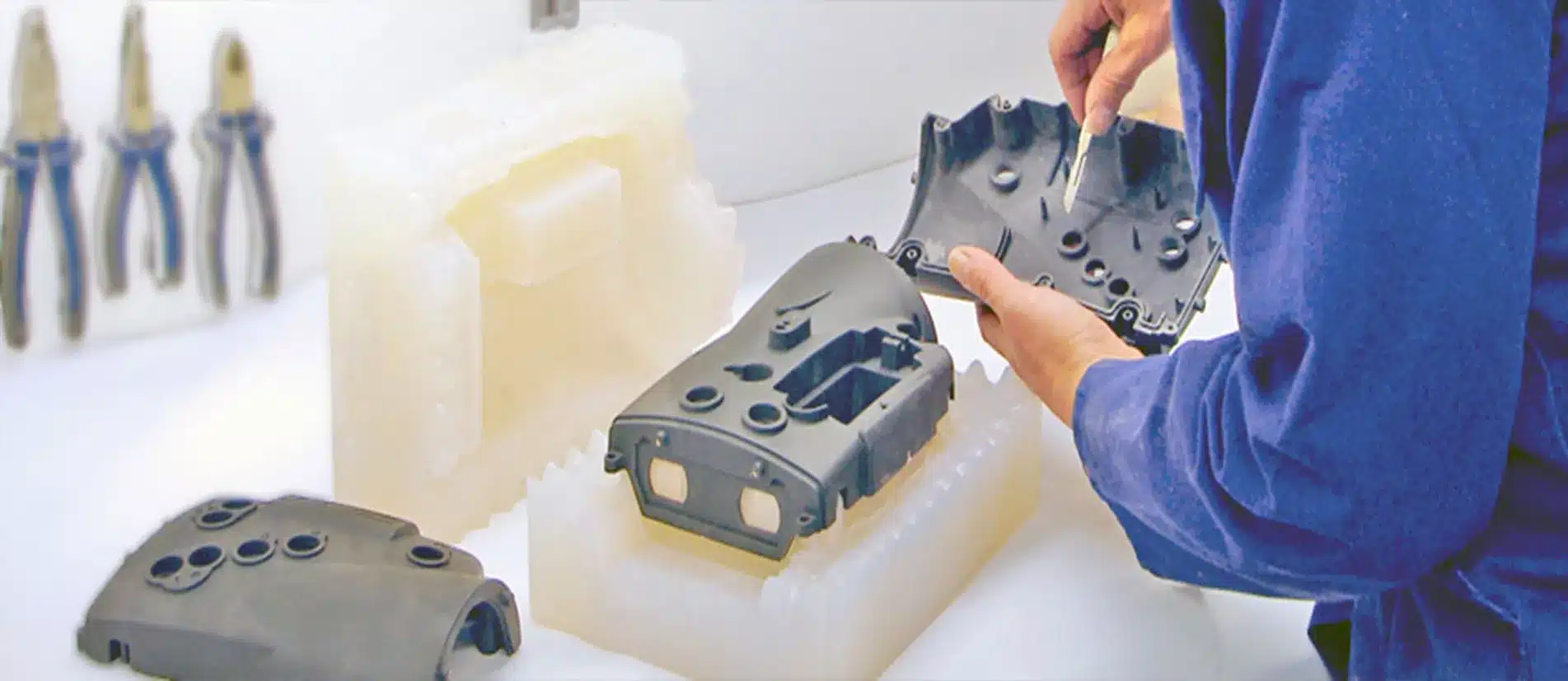
Rapid Prototyping
CNC machining, 3D printing, and vacuum casting can be used to evaluate designs, interfaces, and functional requirements during product development.
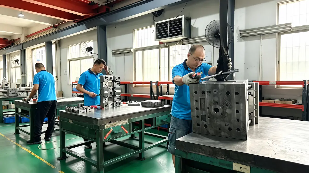
Mold Making
In-house mold design and manufacturing supports projects requiring dedicated production tooling and controlled tooling development.
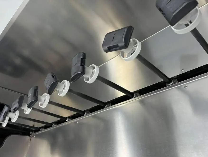
Surface Finishing
Polishing, passivation, laser marking, and other finishing processes can be integrated when the final application requires more than the as-sintered surface condition.
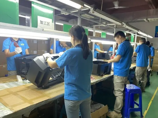
Product Assembly
For projects involving multiple metal or plastic components, assembly and related post-production services can help move the project from individual parts to finished products.
Need More Than MIM?
Send us your complete part requirements. We can help identify the right combination of MIM, machining, finishing, and assembly for your final product.
Metal Injection Molding FAQ
Still evaluating a MIM project? Here are practical questions buyers and engineers often need answered before requesting a quotation.
For an initial quotation, we typically need a 3D CAD model, 2D drawing if available, material requirements, estimated annual volume, and any critical functional or quality requirements. Additional information can be confirmed during the engineering review.
Yes. An existing CNC-machined, cast, or conventionally manufactured metal part can be reviewed to determine whether its geometry and production requirements are suitable for MIM and whether design changes could improve manufacturability.
Yes. Our engineering team can review the available CAD data and identify potential manufacturing concerns before tooling begins. This allows design decisions to be addressed earlier rather than after mold manufacturing.
Engineering changes can be evaluated based on their effect on the existing tooling and production process. Minor changes may require tooling modification, while major geometry changes may require a different tooling approach.
Yes. Confidential product information and engineering files can be handled under an NDA when required by the customer.
MIM economics generally become more attractive as production volume increases because tooling and process development costs are distributed across more parts. We can review your expected volume and recommend whether MIM is appropriate for the project.
Yes. Sample production and validation can be arranged before moving into regular production, depending on the project requirements and tooling strategy.
Yes. Existing tooling can be reviewed to determine its condition, compatibility, and suitability for the required MIM production process. We can also evaluate whether tooling modification or replacement is necessary before production.
Yes. Existing MIM projects can be evaluated based on the available CAD data, drawings, tooling information, material specifications, production history, and quality requirements. This helps determine the most practical approach for transferring production.