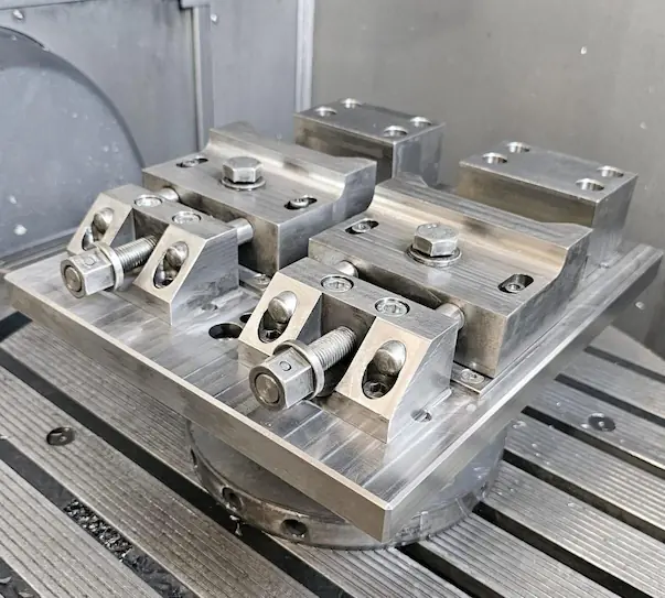
Custom Assembly Fixture Manufacturer

Custom Assembly Fixture Design & Manufacturing

SENSES MOLD designs and manufactures custom assembly fixtures for component alignment, fastening, press-fit insertion and bonding. We turn your part drawings and assembly requirements into tooling that locates, supports and holds components during production.

From fixture design and component machining to assembly and agreed inspection, we define the build around your process. Send part CAD models for design and build, or approved fixture drawings for manufacturing.

  • Custom-Machined Bases, Locators & Supports
  • Fixture Assembly & Checks Against Agreed Acceptance Criteria

For quotation, share your drawings, assembly operation, fixture quantity, critical dimensions and target delivery date.
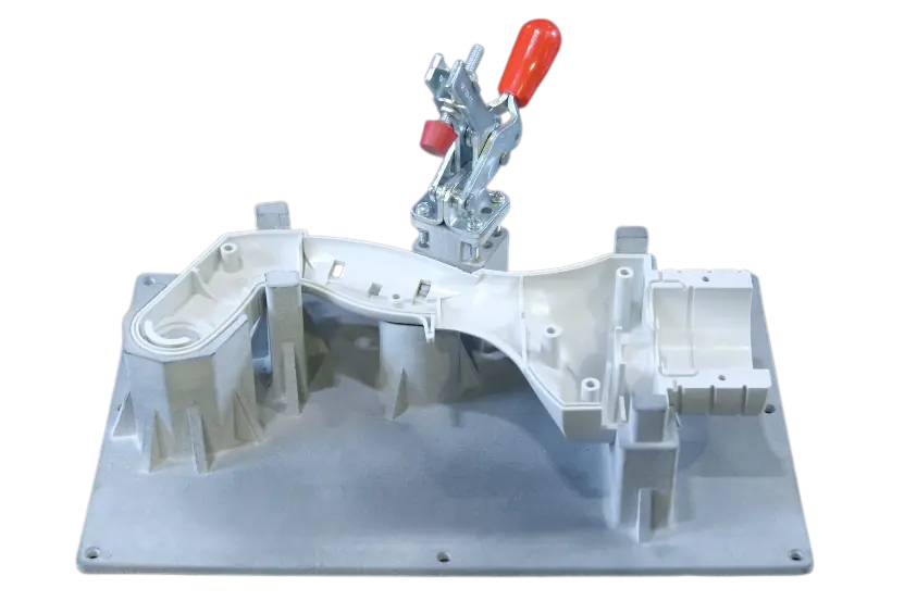
Assembly fixture with locating pins, support blocks and toggle clamps
US$200–800* Manual Assembly Jig Budget Reference
5–10 Business Days* Manual Assembly Jig Lead-Time Reference
Design & Build Fixture Design, Machining & Assembly

*Preliminary references for manual assembly jigs only. Custom fixture pricing and lead time depend on design scope, components and inspection requirements. Your quotation defines the delivery schedule, its start point and shipping terms.

Engineering, Manufacturing & Verification

Assembly Fixture Capabilities at a Glance

From component drawings to finished tooling, SENSES MOLD supports assembly fixture projects through requirement review, custom design, manufacturing and agreed verification. Define the inputs and acceptance criteria before the build.

01 / REQUIREMENT REVIEW

Drawing & Process Review

Review the parts and assembly operation to identify what the fixture must locate, support and hold.

  • Component drawings and 3D CAD
  • Assembly sequence and process loads
  • Datums and critical dimensions

Define: Design inputs, open questions and project scope.

02 / FIXTURE DESIGN

Locating & Clamping

Develop the fixture arrangement around part geometry, incoming variation and the assembly sequence.

  • Locating pins, nests and supports
  • Clamp positions and tool clearance
  • Loading and finished-part removal

Define: The locating scheme and design approval requirements.

03 / MANUFACTURING

Component Build & Assembly

Manufacture tooling components to approved drawings, then complete mechanical fitting and assembly.

  • Base plates and locating components
  • Supports, clamps and purchased hardware
  • Fit, movement and clearance checks

Define: Materials, drawing revisions and included components.

04 / VERIFICATION

Inspection & Functional Checks

Check specified fixture characteristics against approved drawings and agreed acceptance criteria.

  • Locator positions and support relationships
  • Component seating and clamp operation
  • Sample-part trials where included

Define: Measurement conditions, limits and required records.

Have part CAD files or an approved fixture design? Send them with your assembly requirements.

Review My Fixture Requirements

Component Positioning & Assembly Control

Assembly Fixtures for Accurate and Repeatable Production

An assembly fixture locates, supports and holds components during fastening, insertion or bonding. At SENSES MOLD, we design and build these functions around your part geometry, assembly datums and operating sequence.

Assembly fixture showing locating pins, support blocks and toggle clamps around a workpiece

Build Location Around Your Part Datums

We review the drawing references and mating features to define the locating scheme, then machine the required nests, stops and locator mounts. Pin clearances and contact positions account for incoming part variation.

Machine Supports for the Assembly Loads

We position supports beneath fastening and insertion loads, then fit clamps at suitable contact points. Protective pads or replaceable supports can be specified for cosmetic surfaces and wear-prone areas.

Check the Loading and Removal Sequence

During fixture assembly and setup, we check part seating, clamp operation and tool access using agreed samples when available. The review includes how the completed assembly is released and removed.

Show us the alignment, gap or assembly dimension you need to control, together with your part drawings.

Discuss My Positioning Requirements
Design Review Example Finished Gap: 2.00 ±0.10 mm

For this example requirement, our design review would consider component tolerances, locating clearance and movement during fastening. A 2.00 mm spacer alone cannot guarantee the gap after clamp release. The value illustrates a design input, not a stated fixture capability or completed project result.

Custom Tooling for Your Assembly Operation

Assembly Fixture Types and Applications

We design and manufacture assembly fixtures for fastening, insertion, bonding and component alignment. Each build combines custom-machined locating and support components with clamps selected for your parts, process loads and tool access.

Fastening assembly fixture holding a mechanical enclosure with toggle clamps
01 / FASTENING

Fastening Assembly Fixtures

We build locating nests and supports to hold housings, covers and brackets during screw or bolt installation. Clamp positions leave access for the specified driver and tightening sequence.

Typical Applications
Enclosures, mechanical housings and bracket assemblies.
Build Requirements
Tightening torque, fastener sequence, driver envelope and surface-protection needs.
Manual press with an insertion assembly fixture supporting a machined component
02 / INSERTION

Insertion Assembly Fixtures

Custom-machined supports and locators position the component beneath the insertion tool. We design the fixture interface around your press, with a defined load path beneath the insertion point.

Typical Applications
Dowel pins, bushings, inserts and connector installation.
Build Requirements
Insertion force, fit, depth, press mounting and available stroke.
Bonding assembly fixture positioning a bezel and frame with perimeter clamps
03 / BONDING

Bonding Assembly Fixtures

We manufacture locating nests, stops and clamping arrangements to maintain component position during adhesive joining. Contact materials and relief features are selected around dispensing, curing and removal.

Typical Applications
Plastic frames, bezels, covers and bonded subassemblies.
Build Requirements
Bond-line thickness, adhesive compatibility, holding time and cure conditions.
Component alignment fixture with two supported brackets and a shared alignment mandrel
04 / ALIGNMENT

Component Alignment Fixtures

Machined supports, locating pins and removable mandrels establish the relationship between mating parts. We configure these features around your datum scheme and the completed assembly’s removal path.

Typical Applications
Mating brackets, shaft supports and multi-part assemblies.
Build Requirements
Datum references, alignment limits, fit clearance and release sequence.

Send your drawings and assembly sequence to discuss the right fixture.

Find the Right Fixture Type

Engineering Review Before Manufacturing

Assembly Fixture Design Considerations

Before machining begins, we review your component geometry, datum references, process loads and assembly sequence. These inputs determine the locating layout, support positions, clamp selection and dimensions released for manufacture.

Assembly fixture with locating pins, support blocks, toggle clamps and screwdriver access

Translate Part Datums into Locating Features

We use your assembly drawing references to define locating pins, stops and seating surfaces. The design review considers pin-to-hole clearance and incoming part variation before locator positions and fits are specified on the fixture drawings.

Design Supports Around Process Loads

Support blocks and clamp positions are planned together to carry fastening or insertion loads. We consider part stiffness, contact area and surface protection when selecting support geometry and clamping components.

Check Tool Access Before Cutting Metal

We review the driver, socket, press tool or dispenser envelope against the fixture layout. Tool dimensions or CAD models help identify interference with clamps, locators and components added later in the sequence.

Plan Loading, Removal and Part Changes

The layout accounts for how parts enter the fixture and how the finished assembly leaves it. Removable locators, replaceable nests and adjustable stops can be incorporated where product variants or maintenance requirements justify them.

Tool Clearance — Calculation Example

Ø20 mm Tool in a Ø24 mm Opening

For concentric circular profiles, nominal radial clearance is (24 − 20) ÷ 2 = 2 mm. Our layout review would also consider alignment variation, tool movement and nearby components before specifying the opening. This is not a universal clearance allowance.

Load Path — Calculation Example

5 N·m Torque at a 50 mm Reaction Arm

With a perpendicular reaction force, the idealized load is 5 ÷ 0.05 = 100 N. This is a load-path calculation, not a clamp-force rating. Component selection also considers geometry, friction, dynamic effects and the required design margin.

Send your CAD models and tool details for a fixture design review.

Review My Fixture Design
Material Selection & Fixture Components

Assembly Fixture Materials and Components

We select assembly fixture materials around your process loads, contact surfaces and working environment. Custom-machined bases, supports and nests are combined with locating and clamping components to suit the approved fixture design.

Aluminum Base Plates

We machine mounting holes, locator interfaces and reference surfaces into the base plate. Plate thickness and support spacing are selected around the fixture footprint, mounting conditions and assembly loads.

Steel Locating Pins & Support Blocks

Custom steel supports and specified locating pins establish part position and carry process loads. We define fits, contact hardness and replacement arrangements for wear-prone components during design.

Stainless Steel Components

Stainless brackets, fasteners and other exposed components can be specified for moisture or cleaning environments. Material selection considers the actual chemicals, contact conditions and required finish.

Polymer Nests & Contact Pads

We machine shaped nests and fit replaceable contact pads to support parts and protect cosmetic surfaces. Polymer selection accounts for pressure, temperature, cleaning fluids and any specified ESD requirements.

Assembly fixture materials and components with aluminum base plate, steel locating pins, stainless steel bracket and polymer nest
Material Options Reviewed Before Manufacturing
Material Fixture Applications Manufacturing & Selection Checks
Aluminum Example: 6061-T6 Base plates, fixture bodies and changeover nests. Plate stiffness, thermal expansion and thread wear. Specify replaceable inserts where repeated contact could damage the aluminum.
Steel Examples: 1045 / 4140 Load-bearing supports and wear components with a specified heat-treatment condition. Required hardness, heat-treatment distortion and corrosion protection. Plan final machining around critical dimensional requirements.
Stainless Steel Examples: 304 / 316 Brackets and exposed components in moisture or cleaning environments. Chemical compatibility, surface finish and contact wear. Grade selection depends on service conditions.
Engineering Polymers Examples: POM / UHMW-PE Protective nests, contact pads and replaceable part supports. Creep, temperature and dimensional stability. Specify a suitable ESD grade when required; standard grades are not assumed ESD-safe.

Grades shown are selection examples. Final materials, heat treatments, finishes and replacement components are defined in the approved fixture specification.

Share your part material and process loads to discuss fixture materials.

Discuss Fixture Materials
Tolerance Planning & Repeatability

Fixture Tolerances, Accuracy and Repeatability

We review your finished-assembly requirements before assigning tolerances to fixture components. Critical dimensions, datum references and acceptance conditions guide the design, machining and verification of locating pins, supports and nests.

Translate Assembly Limits into Fixture Tolerances

We review the dimensional stack between mating parts, locating features and fixture contacts. This helps allocate tolerances to the machined components while accounting for part variation, clearance and deformation.

Specify Accuracy and Repeatability Separately

The acceptance plan distinguishes closeness to the target position from variation after reloading. We agree on which characteristics to check because consistent seating alone does not confirm that the assembly is correctly positioned.

Control Fits, Contact Points and Clamp Settings

We specify locating fits and support geometry on the fixture drawings, then check seating and clamp contact during setup. For flexible parts, the review also addresses movement or distortion after clamp release.

Match Inspection to the Required Result

Before the build, we agree on the features, datum alignment and measurement conditions used for acceptance. Temperature effects and measurement uncertainty are considered where they could affect the result.

Illustrative Tolerance Calculation

Assembly Requirement: 100.00 ±0.10 mm

0.03 + 0.04 + 0.02 = 0.09 mm
Worst-case variation: ±0.09 mm

For a simple one-dimensional stack with unit sensitivity coefficients, assume part A contributes ±0.03 mm, part B ±0.04 mm, and the fixture is allocated ±0.02 mm. The worst-case sum leaves 0.01 mm per direction for other effects.

The actual allocation depends on the assembly geometry, locating clearances and process conditions.

Illustrative Reload Test

30 Reload Cycles with One Reference Part

25.022 − 25.006 = 0.016 mm range

If a feature measured after each reload ranges from 25.006 mm to 25.022 mm, the observed peak-to-peak range is 0.016 mm under those test conditions.

The range includes measurement variation. It does not establish ±0.008 mm accuracy or production capability across different parts and operators.

What We Confirm Before Manufacturing

01 — Drawing and Critical Features

Confirm the drawing revision, datum references and gaps, positions, heights or alignments that the fixture must help control.

02 — Setup and Test Conditions

Agree on sample parts, clamp settings, reload cycles and whether measurements apply with the assembly clamped or released.

03 — Acceptance and Delivery Records

Define the dimensional results, repeatability data and finished-assembly checks included in the agreed inspection scope.

Numerical examples explain calculation and test methods; they are not SENSES MOLD capability specifications or measured project results. Fixture tolerances and acceptance limits are confirmed through drawing review and an agreed verification plan.

Send your drawings and critical dimensions for a tolerance review.

Review My Tolerance Requirements
From Drawing Review to Delivery

Assembly Fixture Design and Manufacturing Process

SENSES MOLD takes your assembly fixture from requirements review through design, component machining, assembly and agreed verification. For build-to-print orders, we review your approved tooling drawings and confirm the manufacturing scope before production.

Requirements Review

We review your 2D drawings, 3D CAD models and assembly operation. Critical dimensions, process loads, fixture quantity and sample availability help define the design scope and quotation requirements.

Project Inputs Confirmed drawing revisions, scope and open technical questions.

Concept & Layout

For design-and-build projects, we develop the locating scheme, support arrangement and clamp positions. The layout review checks loading, tool approach and removal against your intended assembly sequence.

Layout Review Proposed fixture configuration and operating sequence.

Detailed Fixture Design

We define component geometry, materials, locating fits and critical tolerances. Purchased clamps, adjustable features and replaceable wear parts are specified before the design is released for manufacturing.

Manufacturing Release Approved revision, component drawings and bill of materials.

Component Manufacturing

We machine the base plate, nests, supports and custom locating components to the released drawings. Specified heat treatments and finishes are sequenced around the final dimensional requirements.

Component Checks Critical dimensions, mating fits and specified finishes.

Fixture Assembly & Setup

We install the locators, supports, clamps and stops, then set adjustable components. Where agreed samples are available, setup includes checking part seating, clamp contact and access for assembly tools.

Setup Checks Component operation, part fit and loading and removal clearance.

Validation & Delivery

We carry out the checks specified in the acceptance plan and record the results. Deviations are reviewed before release, and the fixture is prepared for shipment with the documentation included in your order.

Agreed Delivery Package Fixture, specified inspection records, instructions and ordered spares.

Design Approval Before Machining

We confirm the manufacturing revision before machining begins. If your part geometry, datum features or assembly tools change afterward, we review the effect on the fixture and confirm any cost or schedule adjustment before implementing the change.

Share your CAD files and target delivery date to plan your fixture build.

Plan My Fixture Build
Inspection Before Delivery

Assembly Fixture Inspection and Validation

Before delivery, we check the assembly fixture against its approved drawings and agreed acceptance plan. Dimensional inspection verifies the tooling; fit and functional checks assess its operation using the specified samples, tools and process settings.

Inspect Drawing-Controlled Features

We check specified locating-pin positions, support heights, nest profiles and mounting interfaces. The inspection method and datum alignment are selected around the feature geometry and tolerance.

Check Fit During Fixture Setup

When agreed sample parts are available, we check seating, clamp contact and assembly-tool access. The setup review includes loading the components and removing the completed assembly without interference.

Verify Repeatability Where Specified

When reload testing is included in the order, we follow the agreed loading and clamping sequence, record the selected feature positions and compare the observed variation with the acceptance limits.

Review Results Before Release

We link inspection records to the fixture revision and test conditions. Results outside the agreed limits are reviewed and resolved before release, with reinspection where adjustments affect acceptance.

Engineer in blue workwear operating a CMM to inspect an assembly fixture
01 / Dimensional Records

Nominal, Tolerance and Actual Result

The agreed dimensional report identifies measured features, drawing requirements and actual results, together with the relevant datum and measurement method.

02 / Functional Checks

Part Fit and Assembly Results

Where included, we record fit and operating checks using identified samples. Finished gaps, alignments or insertion depths are assessed in the specified clamped or released condition.

03 / Repeatability Example

30 Reload Cycles × 3 Features

An example trial measures 3 features after each of 30 reload cycles, producing 90 readings. The observed range is evaluated separately for each feature.

The reload trial illustrates a possible test plan, not a universal acceptance standard, measured project result or gauge R&R study. Inspection scope, equipment, sample requirements and delivery records are agreed for each order.

Share your acceptance criteria and required records to plan fixture inspection.

Discuss My Inspection Plan

Custom Fixture Applications

Custom Assembly Fixtures We Design and Build

From protective nests for plastic housings to rigid supports for press-fit operations, we design and manufacture tooling around your assembly requirements. These application examples show how the fixture configuration and inspection scope can be defined for different parts.

Plastic housing assembly fixture with protective nest and toggle clamps
Plastic Components / Screw Assembly

Plastic Housing Assembly Fixture

Assembly Requirement
Hold a molded housing and cover during screw installation while protecting visible surfaces and keeping fasteners accessible.
Our Fixture Solution
We machine a shaped nest and supporting base, then fit protective pads and clamps positioned around the housing’s reinforced contact areas.
Agreed Acceptance Checks

Part seating, driver access, cover gap and cosmetic condition after unclamping.

Press-fit assembly fixture aligning a bronze bushing under an arbor press
Machined Components / Bushing Insertion

Press-Fit Assembly Fixture

Assembly Requirement
Position a machined body for bushing insertion and react the pressing load without bending or damaging the component.
Our Fixture Solution
We build a rigid reaction support and locating arrangement matched to the part geometry, insertion axis and specified press interface.
Agreed Acceptance Checks

Tool alignment, insertion depth and part condition. Force monitoring requires an instrumented press.

Bonding and alignment fixture holding an aluminum frame and panel
Frames & Panels / Adhesive Assembly

Bonding and Alignment Fixture

Assembly Requirement
Maintain frame-to-panel alignment during adhesive joining and the specified holding period, with access for loading and release.
Our Fixture Solution
We machine the locating nest and datum stops, then fit protective clamp pads and adhesive-relief features suited to the bonding sequence.
Agreed Acceptance Checks

Frame-to-panel alignment and specified bond-line requirements after the agreed cure and release.

Have a similar assembly? Send your drawings to discuss the fixture build.

Request a Fixture Manufacturing Quote
Budget Planning & Production Scheduling

Assembly Fixture Cost and Lead Time

We quote each assembly fixture against its design scope, machined components, purchased hardware and acceptance requirements. Drawing review establishes what must be manufactured and which activities determine the delivery schedule.

Preliminary Planning Reference

Manual Assembly Jigs

US$200–800* Budget reference for manual assembly jigs.
5–10 Business Days* Lead-time reference, subject to the confirmed scope and schedule start point.

*These references are not fixed quotations or delivery commitments and do not apply automatically to complex, pneumatic or automated fixtures. Confirm design, inspection, shipping and other inclusions in your quotation.

Design Scope and Drawing Readiness

A fixture developed from part CAD requires locating, clamping and tolerance decisions before machining. Approved tooling drawings reduce design work, but still require a manufacturing review.

Part Count, Materials and Machining

Fixture size, nest geometry, number of setups and critical tolerances affect machining time. Heat treatment, finishing and replaceable wear components add operations or purchased parts.

Clamps, Actuation and Purchased Hardware

Manual clamps, pneumatic components, sensors and quick-change hardware carry different costs and procurement times. We confirm the specified components before committing to a build schedule.

Samples and Acceptance Testing

Trial assembly, reload testing and additional records affect inspection effort. If acceptance depends on customer parts or tools, their arrival date must be included in the schedule.

What We Confirm in Your Project Quotation

01 — Manufacturing Scope

Design responsibility, fixture quantity, materials, purchased components and any ordered spare nests, locators or contact pads.

02 — Schedule and Start Point

The agreed start conditions, such as drawing approval, order confirmation or sample receipt, plus the planned completion or dispatch date.

03 — Inspection and Delivery

Acceptance checks, documentation, packaging and shipping terms. Transit time and any excluded charges are identified separately.

Send your drawings and required delivery date for a project-specific estimate.

Get Pricing & Lead Time
Drawings & Project Requirements

What Information Is Needed for an Assembly Fixture Quote?

Send the information below so we can define the fixture design, machining, purchased components and inspection scope. For build-to-print orders, include your approved tooling drawings and bill of materials.

Part Drawings & CAD

Include models of the components being assembled, dimensioned drawings and the finished assembly layout. Identify the current revision and part materials.

Suggested package: STEP models plus PDF drawings showing tolerances, datums and surface requirements.

Assembly Operation

Describe the loading, fastening, insertion or bonding sequence. Identify the step that needs positioning, support or operator guidance.

Useful details: Process photos or video, tightening torque, insertion force and adhesive cure conditions.

Critical Dimensions

Mark the gaps, alignments, positions or insertion depths the assembly must meet. State whether the requirement applies while clamped or after release.

Include: Nominal values, tolerances, datum references and the required acceptance method.

Tools & Workstation

Provide the mounting interface and available workspace. Include the tools that must reach the part, together with their approach and withdrawal directions.

Include where applicable: Press stroke, driver dimensions, mounting-hole pattern and available air supply.

Quantity & Product Variants

State how many fixtures you need and how many part variants each must accommodate. Separate fixture quantity from expected assembly production volume.

Also specify: Changeover requirements, spare nests or locators, and any target operating cycle.

Samples, Records & Delivery

Confirm whether sample parts are available for setup and testing. List required inspection records and your target delivery date and destination.

Clarify the deadline: Required dispatch date or arrival date, plus when samples can reach us.

Do Not Have a Complete Fixture Specification?

Start with the available part drawing or CAD model, a description of the assembly operation and the problem you need to solve. We review the inputs and identify what is still needed before confirming the design scope, price and manufacturing schedule.

Share your available drawings and project requirements to start the review.

Submit My Fixture Requirements
Engineering, Manufacturing & Delivery

Why Choose SENSES MOLD for Assembly Fixtures?

We connect fixture design with component machining, assembly and agreed inspection. Your drawings and production requirements define the build, while the quotation establishes responsibilities, deliverables and acceptance criteria.

Design Connected to Manufacturing

We review how locators, supports and clamp mounts will be machined and assembled before releasing the design. Functional requirements are translated into component drawings, fits and adjustment points.

Design-and-Build or Build-to-Print

Send part CAD and assembly requirements for a new fixture design, or approved tooling drawings for manufacturing. We confirm design responsibility and identify missing inputs before work begins.

Inspection Against Defined Requirements

We agree on the dimensions, samples and functional checks used for acceptance. Required inspection records are linked to the fixture revision and specified test conditions.

Planned Changes and Replaceable Parts

We review the manufacturing impact of part revisions before implementing changes. Replaceable locators, contact pads and nests can be specified for wear, maintenance or product variants.

Engineer in blue workwear adjusting a custom assembly fixture at a workshop bench

Know What Your Order Includes

The agreed scope identifies the fixture quantity, design work, materials, purchased components, inspection records and delivery terms. Setup instructions and spare components are included where specified, giving your production team a clear basis for receiving the tooling.

Tell us what your production team needs from its next assembly fixture.

Discuss Working with SENSES MOLD
Assembly Fixture Questions

Frequently Asked Questions About Assembly Fixtures

Answers to common questions about fixture design, manufacturing, materials, inspection and quotation.

What is an assembly fixture?

An assembly fixture locates, supports and holds components in a defined relationship during fastening, insertion or bonding. Locating features establish position, while supports and clamps help maintain that position under the expected process loads.

How does an assembly jig differ from a fixture?

In traditional tooling terminology, a jig holds the workpiece and guides a tool, while a fixture primarily locates and holds the workpiece. In assembly work, the names are sometimes used interchangeably. We define the required locating, holding and tool-guiding functions when reviewing your project.

Can you design a fixture from my part CAD?

Yes. We can develop an assembly fixture design from part CAD models together with your assembly sequence, critical dimensions and process requirements. Include drawings showing tolerances, datums and surface requirements not captured in the model.

For build-to-print manufacturing, send the approved fixture drawings and bill of materials.

Which materials are suitable for assembly fixtures?

Options include 6061-T6 aluminum for base plates, appropriately specified steel for loaded or wearing components, and POM or UHMW-PE for protective nests and contact pads.

We select grades, treatments and finishes around load, wear, temperature and surface requirements. ESD applications require a suitable material grade.

What accuracy and repeatability can you achieve?

We confirm requirements after reviewing geometry, datums, locating clearances, process loads and the measurement method. A tolerance on one machined component does not establish finished-assembly accuracy.

Positioning accuracy and reload repeatability are specified separately, with acceptance limits and test conditions agreed before manufacturing.

Do you need physical sample parts?

Drawings and CAD models can support design and manufacturing. Physical samples are needed when agreed acceptance checks depend on actual fit, clamping behavior or the completed assembly.

We confirm sample quantity and timing during review. Additional samples may be needed to assess part variation.

How do you inspect and validate the fixture?

We inspect specified dimensions against approved drawings. Where included, we also check seating, clamp operation, tool access and finished-assembly features using agreed samples and settings.

An example reload test measures 3 features over 30 cycles, producing 90 readings. This is an example plan, not a universal requirement or a gauge R&R study.

Can one fixture accommodate multiple part variants?

Yes, where geometry and datum requirements allow it. Interchangeable nests, removable locators or adjustable stops can be considered instead of separate complete fixtures.

Send CAD models for every variant so we can review changeover, adjustment control and acceptance checks for each configuration.

How much does a custom assembly fixture cost?

The preliminary manual assembly jig budget reference is US$200–800. This is not a fixed quotation or a range for every fixture type. Design scope, size, materials, hardware and inspection requirements determine the project price.

Send drawings and fixture quantity for a quotation identifying inclusions, exclusions and delivery terms.

What is the lead time for an assembly fixture?

The preliminary manual assembly jig reference is 5–10 business days, subject to confirmed scope and the schedule start point. Custom designs, special components, treatments and testing can require additional time.

Your quotation defines start conditions and the planned completion or dispatch date. Transit time is confirmed separately.

Have a question about your parts or assembly operation?

Ask About My Fixture Project

Assembly Fixture Buying & Engineering Guides

Assembly Fixture Guides from a Manufacturer’s Perspective

Our guide topics focus on the decisions that connect fixture design with machining, assembly and inspection. Explore how to compare tooling options, investigate production problems and prepare clearer purchasing requirements.

Compare Your Options

Understanding & Selection

Choose a fixture approach that fits your components, assembly operation and production volume.

  • Types of Assembly Fixtures: Applications and Selection Guide
  • Assembly Jig vs. Assembly Fixture: Which Functions Do You Need?
  • Modular vs. Dedicated Assembly Fixtures: Which Fits Your Production?
  • Manual vs. Semi-Automated Assembly Fixtures: When to Upgrade
Solve Production Problems

Design & Workholding

Review datums, locating features and clamp positions before releasing the fixture for manufacturing.

  • Assembly Fixture Design Checklist: 10 Checks Before Manufacturing
  • How to Choose Datums and Locating Pins for an Assembly Fixture
  • Why Parts Shift During Fastening—and What to Check First
  • How to Use Poka-Yoke in Assembly Fixture Design
Check Tools & Workstations

Process & Equipment Compatibility

Define how the fixture interfaces with assembly tools, presses and the operator’s working sequence.

  • Press-Fit Assembly Fixtures: Support, Alignment and Load-Path Checks
  • Screw Assembly Fixtures: Driver Access and Torque Reaction
  • Bonding Assembly Fixtures: Bond-Line Control, Cure and Release
  • Assembly Fixture Changeover: Designing for Multiple Part Variants
Plan for Service Life

Materials & Maintenance

Select bases, nests and wear components around stiffness, surface protection and replacement needs.

  • Aluminum vs. Steel Assembly Fixture Bases: How to Choose
  • Polymer Nests and Contact Pads for Plastic Part Assembly
  • Manual vs. Pneumatic Clamps for Assembly Fixtures
  • When to Replace Locating Pins, Bushings and Fixture Contact Pads
Define Acceptance

Inspection & Validation

Separate fixture performance from part variation and agree on checks that reflect the assembly requirement.

  • Assembly Fixture Accuracy vs. Repeatability: What Is the Difference?
  • How to Plan an Assembly Fixture Reload Repeatability Test
  • Fixture Tolerance Stack-Up: From Part Drawings to Assembly Limits
  • Assembly Fixture Acceptance Checklist: What to Verify Before Shipment
Prepare Your Purchase

Cost & Supplier Evaluation

Prepare comparable quotations and clarify design, manufacturing and inspection responsibilities.

  • How Much Does a Custom Assembly Fixture Cost? A Buyer’s Budget Guide
  • Build-to-Print vs. Design-and-Build Assembly Fixtures
  • 10 Questions to Ask an Assembly Fixture Manufacturer Before Ordering
  • Assembly Fixture RFQ Checklist: Drawings, Samples and Acceptance Requirements

Planned guide topics. Article links will be added as the guides are published.

Need help applying these ideas to your fixture project?

Discuss My Engineering Questions

Get your quote

Fill out the contact form below,  and you will get your quote within 24 hours.

Email: info@senseschina.com

WhatsApp: +8613790527236