
Custom Rubber Compression Mold Manufacturer
Precision Tooling from Prototype to Mass Production
We design and manufacture custom compression molds for rubber parts — delivering ISO & IATF 16949-certified quality to automotive, medical, and industrial clients in 38+ countries. From single-cavity prototypes to high-volume multi-cavity compression molds, all in-house.
- 7–15 Days tooling lead time
- 100+ Countries served globally
- ±0.005mm Compression mold tolerance capability
- 20+ years Compression mold manufacturing experience
- Free DFM Review
- FDA-Grade Available
- RoHS / REACH
- NDA Available
- ISO 9001 Certified
- IATF 16949 Certified
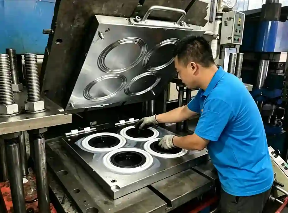
Compression Molding Parts We produced


Compression Mold Applications: Industries & Rubber Parts We Serve
Rubber compression molding is used across industries wherever durable, precision rubber parts are required. Below are the key sectors we serve and the typical parts we produce.
Automotive
Compression molds for door seals, weatherstripping, anti-vibration mounts, EPDM gaskets, and engine bay grommets.
EPDM
NBR
IATF 16949
Automotive compression mold
Medical
FDA-compliant silicone compression molds for diaphragms, valve seals, syringe components, and peristaltic pump parts.
Silicone
FDA 21 CFR
ISO 13485
Medical silicone compression mold
Aerospace
FKM and silicone compression molds for aircraft seals, vibration isolators, fuel system O-rings, and rubber-to-metal bonded parts.
FKM / Viton
Silicone
AS9100
Aerospace rubber compression mold
Industrial
NBR and HNBR compression molds for pump seals, pipe gaskets, hydraulic bladders, valve seats, and chemical-resistant components.
HNBR
NBR
FKM
Industrial rubber compression mold
Electronics
Silicone and EPDM compression molds for keypad buttons, waterproof seals, cable grommets, and shock-absorbing pads.
Silicone
EPDM
RoHS
Electronics rubber compression mold
Construction
EPDM and Neoprene compression molds for bridge bearing pads, expansion joint seals, and curtain wall gaskets.
EPDM
Neoprene
UV resistant
Construction rubber compression mold
Don’t see your industry? We work across all sectors.
Tell us your application and material requirements — our engineers will confirm if compression molding is the right process and quote within 24 hours.
What Is a Compression Mold?
A compression mold is a precision tooling set used to shape rubber or elastomer materials by placing a pre-measured compound into a heated mold cavity, then applying hydraulic pressure until the material vulcanizes into its final form.
Unlike injection or transfer molding, compression molding requires no runner system or sprue — the raw rubber is loaded directly into the open mold cavity. This makes compression molds simpler in design, lower in tooling cost, and particularly well-suited for medium-hardness compounds, large cross-section parts, and low-to-mid volume production runs.

How the compression molding process works
Compression molding is a highly reliable and cost-effective manufacturing process ideal for medium to high volume production of rubber parts. Pre-weighed rubber compound is placed into a heated mold cavity. As the press closes, the combination of heat and hydraulic pressure forces the material to fill the cavity and cure completely. Explore our standard 5-step workflow below.
Step 1
Material preparation — preform cutting
Raw rubber compound is cut or pre-formed into a “preform” — slightly more material than the finished part requires, ensuring full cavity fill without voids.
Step 2
Mold loading — place preform in open cavity
The preform is placed manually into the lower half of the open compression mold cavity before the press closes.
Step 3
Compression & cure — heat + hydraulic pressure
The compression mold press closes under hydraulic pressure (50–200 tons), applying heat (150–200°C) simultaneously. The rubber flows to fill the cavity and vulcanizes.
Step 4
Demolding — part ejection and flash trim
Once cure time is complete, the mold opens and the finished rubber part is removed. Excess flash along the parting line is trimmed.
Step 5
Inspection — dimensional check to ±0.05mm
Each part is measured against the drawing. Our standard capability reaches ±0.05mm on critical dimensions
Key Technical Parameters — Compression Mold at a Glance
The table below summarizes the standard operating parameters for rubber compression molding. These figures reflect our in-house production capabilities:
Mold temperature
150 – 200°C
Clamping pressure
50 – 200 ton
Cure time
2 – 15 min
Dimensional tolerance
±0.05 mm
Shore hardness range
20 – 90 Shore A
Compression Mold vs Injection Mold vs Transfer Mold
Choosing the wrong molding process costs weeks of rework and thousands in retooling. Here is a direct comparison of the three main rubber molding methods.
Side-by-side comparison
| Criteria | Compression Mold | Injection Mold | Transfer Mold |
|---|---|---|---|
| Tooling cost | Lowest $500–$3,000 | $5,000–$50,000 | $2,000–$8,000 |
| Lead time | Fastest 7–15 days | 15–40 days | 15–40 days |
| Part complexity | Simple to medium | High complexity | Medium complexity |
| Dimensional accuracy | ±0.005 mm | ±0.005 mm | ±0.005 mm |
| Best suited for | Large parts, thick sections, silicone & EPDM | Small, high-volume, tight tolerance | Parts with metal inserts |
When to choose each process
Choose compression mold when:
- Tooling budget under $3,000
- Part is large or thick-walled
- You need fast prototype tooling
- Volume 500–50,000 pcs per run
- Material is silicone, EPDM, or NR
Choose LSR injection mold when:
- Volume exceeds 100,000 pcs
- Need tight tolerance ±0.005mm
- Complex geometry with undercuts
- LSR liquid silicone required
Choose transfer mold when:
- Part has metal inserts to encapsulate
- Part is large or thick-walled
- Tighter tolerance than compression
- Mid-volume, medium complexity
Real Cost Comparison: Tooling + Per-Part Price
Most manufacturers avoid publishing pricing. We believe transparency saves everyone time. Below are realistic cost ranges based on our 20+ years of production data:
Compression Mold Price
Per-part: $0.01+
LSR Mold Price
Per-part: $0.05+
Transfer Mold Price
Per-part: $0.05+
Final cost depends on part size, cavity count, steel grade, and tolerance requirements.
Request a free quote to get an exact figure for your project — typically within 24 hours.
Compression Mold Design Guidelines: What Every Engineer Needs to Know
Poor compression mold design is the single biggest cause of part defects, flash problems, and tooling rework. The following guidelines are based on our 20+ years of designing and manufacturing rubber compression molds — each rule includes specific values your engineering team needs.
7 Critical Compression Mold Design Rules
01
Draft angle — always allow for easy demolding
All vertical walls in a compression mold cavity need a minimum draft angle to prevent the cured rubber part from tearing during ejection. Insufficient draft is the most common cause of surface damage on soft rubber parts.
Minimum: 0.1° for soft rubber (Shore A <50) · 0.5° for hard rubber (Shore A >70)
02
Wall thickness — uniform cross-section prevents sink and void
Uneven wall thickness causes differential cure rates, leading to internal voids or surface sink marks. Design all cross-sections as uniform as possible, or use gradual transitions rather than abrupt changes.
Recommended: 2–12 mm uniform wall · Max variation: <30% between adjacent sections
03
Parting line placement — where you put it matters
The parting line is where flash forms. Place it at the largest cross-section of the part to minimize visible flash on functional surfaces. Avoid placing parting lines across sealing faces or any surface that contacts another component.
Flash thickness target: <0.1 mm at parting line with proper land design
04
Flash land width — controls material flow and flash thickness
The flash land is a flat zone around the cavity that controls how much material escapes. Too narrow causes excessive flash; too wide prevents proper cavity fill. This dimension is critical in compression mold tooling design and is often overlooked in generic CAD designs.
Recommended land width: 1.5–3 mm · Land clearance: 0.02–0.05 mm
05
Preform volume — slightly overfill, never underfill
The rubber preform must be slightly larger than the cavity volume (typically 3–8% excess) to ensure complete fill and proper flash formation. Underfilling causes knit lines and incomplete parts; overfilling increases flash but can be trimmed.
Preform volume: cavity volume × 1.03–1.08 (material-dependent)
06
Shrinkage compensation — design the mold larger than the part
All rubber compounds shrink after demolding as they return to ambient temperature. The compression mold cavity must be machined larger than the target part dimensions by the material’s shrinkage factor. Failure to account for shrinkage is the most common first-shot dimensional failure.
Typical shrinkage: EPDM 1.5–2.5% · Silicone 2.0–3.0% · NBR 1.2–2.0% · NR 1.5–2.5%
07
Steel selection — match hardness to production volume
Not all compression molds need the same steel grade. Prototype or low-volume molds can use softer steel (P20) to reduce tooling cost and lead time. High-volume or abrasive compound molds require hardened tool steel for longevity.
Prototype (<5,000 pcs): P20 steel · Production (5,000–500,000 pcs): H13 hardened · High-abrasion: S136 stainless
5 Common Compression Mold Design Mistakes — and How to Fix Them
These are the most frequent design errors we see in customer-submitted drawings — and the corrections that prevent costly tooling rework:
1. Zero draft on tall cavity walls
The Mistake
Designers copy injection mold geometry directly into compression mold designs without adding draft. Soft rubber parts (Shore A <50) with vertical walls tear on demolding, leaving surface tears and requiring manual trimming every cycle.
The Fix
Fix: Add minimum 1.5° draft to all walls. For textured surfaces, increase to 3°+ to allow texture relief during ejection.
2. Shrinkage not accounted for in cavity dimensions
The Mistake
Designers copy injection mold geometry directly into compression mold designs without adding draft. Soft rubber parts (Shore A <50) with vertical walls tear on demolding, leaving surface tears and requiring manual trimming every cycle.
The Fix
Fix: Add minimum 1.5° draft to all walls. For textured surfaces, increase to 3°+ to allow texture relief during ejection.
Mistake 3: Parting line placed on sealing surface
The Mistake
When the parting line crosses a sealing face or O-ring groove, flash forms directly on the functional sealing surface. Even minimal flash causes leak paths in pressure applications.
The Fix
Fix: Relocate the parting line to a non-functional face during DFM. This is a mold design decision, not a part design change.
Mistake 4: Abrupt wall thickness changes
The Mistake
Sharp transitions between thick and thin sections cause differential cure rates. Thick sections cure more slowly, leaving under-cured cores while thin sections overcure, leading to brittleness.
The Fix
Fix: Use tapered transitions at a minimum 1:3 ratio (thickness change over length). If geometry requires abrupt changes, adjust cure time to the thickest section.
Mistake 5: Under-specified preform dimensions
The Mistake
Drawings arrive with part geometry only, no preform specification. The press operator cuts preforms by eye, leading to inconsistent fill, variable flash thickness, and shot-to-shot weight variation above ±5%
The Fix
Fix: Define preform weight and dimensions on the process sheet — not just the mold drawing. We provide full process documentation with every compression mold we ship.
Rubber Materials for Compression Molding: How to Choose the Right Compound
Selecting the wrong rubber compound leads to premature part failure, regulatory rejection, or unnecessary cost. This guide covers the five most common materials used in compression molding — with real performance data.
Compression mold rubber materials comparison
| Material | Temp range | Oil resistance | Weather / UV | Cost | Best for |
|---|---|---|---|---|---|
| EPDM | −40 to 150°C | Poor | Excellent | Low | Automotive seals, outdoor |
| Silicone | −60 to 230°C | Medium | Excellent | Medium | Medical, food-grade, high-temp |
| NBR | −30 to 120°C | Excellent | Poor | Low | Oil seals, fuel systems |
| FKM (Viton) | −20 to 200°C | Excellent | Excellent | High | Aerospace, chemical seals |
| NR (Natural) | −50 to 80°C | Poor | Poor | Very low | Vibration dampers, general |
| HNBR | −30 to 150°C | Excellent | Medium | Medium | Automotive under-hood, refrigeration |
Stop Guessing. Let Experts Validate Your Material Spec.
Choosing the wrong compound does more than cause leaks – it wastes money. Over-specifyying can increase your unit price by uo to. Tell us your operation environment, and our engineering team will provide a Free Material & DFM review within 24 hours to ensure you get maximum performance at the lowest possible cost.
How We Make Your Compression Mold: From Drawing to Delivery in 15 Days
Every compression mold we produce follows the same rigorous six-stage process — with quality checks built in at each stage, not just at the end.
15 Days
From Drawing to Delivery
6 Stages
Controlled process flow
QC
Built into every step

01
RFQ & free DFM analysis
You send us your drawing (DXF / STEP / PDF). Our compression mold engineer reviews it for DFM — checking draft angles, wall thickness, parting line, shrinkage, and tolerance feasibility. We flag issues before tooling starts.
02
Compression mold design & 3D modeling
Our CAD team designs the full compression mold tooling — cavity, core, flash land, ejection system, and mold base. Shrinkage compensation is applied. You review and approve before any steel is cut.
03
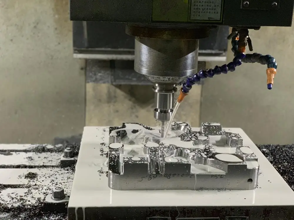
Steel procurement & CNC rough machining
Steel is selected based on production volume — P20 for prototypes, H13 hardened for production, S136 stainless for medical. CNC rough machining removes bulk material to within 0.3 mm of final cavity dimensions.
04
Precision finishing & surface treatment
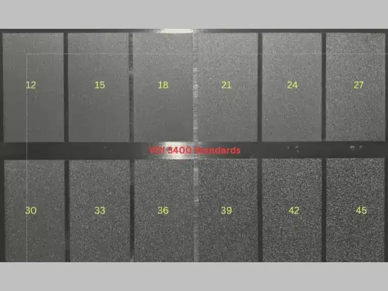
EDM and precision grinding bring cavity dimensions to ±0.005 mm final tolerance. Cavity surfaces are polished or textured to spec. Flash land is precision-ground to control flash thickness.
05
Trial molding & T1 sample approval
T1 samples are measured against your drawing — dimensions, hardness, appearance, and flash. Samples ship to you for approval or measured in-house against a customer-supplied measurement report.

06
Mold delivery or mass production launch
Upon sample approval, we ship the mold with full documentation (drawing, steel cert, maintenance guide) or launch mass production in-house. All molds stored in our library for repeat orders at no extra tooling cost.
Ready to launch in 15 days? Stop guessing on mold costs.
Upload your 3D model today for a secure, zero-obligation review. We’ll reply within 24 hours with an exact quote and a comprehensive DFM analysis. Let’s validate your design and catch potential issues before we cut any steel.
Compression Mold Case Studies: Real Problems We Solved
Three real projects from our production floor — each with a specific engineering challenge, the solution we developed, and the measurable outcome.
Automotive
EU Client
EPDM door seal compression mold
Tight tolerance on complex asymmetric profile
The problem
Multi-cavity compression mold needed for EPDM door seal with complex asymmetric cross-section. Previous supplier delivered T1 samples 12% out of tolerance on the critical sealing lip, causing OEM assembly rejection. Previous lead time: 45 days.
Our solution
Redesigned parting line to avoid flash on sealing lip, applied 2.1% EPDM shrinkage compensation on critical dimension, EDM finishing to Ra 0.8 μm. 6-cavity H13 hardened mold completed in 12 days.

Medical
US Client
FDA-grade silicone compression mold
clean room compatible S136 stainless tooling
The problem
Medical device manufacturer needed FDA 21 CFR 177.2600-compliant silicone diaphragm compression molds. Required flash-free sealing edge, S136 stainless steel mold for IPA cleaning compatibility, and full FDA-submission documentation — none of which the previous supplier could provide.
Our solution
4-cavity S136 stainless compression mold with precision-ground flash land achieving <0.05mm flash on sealing edge. Electropolished to Ra 0.2 μm. Full material traceability, steel cert, compound CoA, dimensional report in FDA-submission format.
Industrial
DE Client
NBR oil seal compression mold
4-to-16 cavity redesign for 62% per-part cost reduction
The problem
Industrial pump manufacturer producing NBR oil seals on a 4-cavity compression mold. Growing order volume made tooling a production bottleneck — cycle time per batch too long to meet delivery commitments at current per-part cost.
Our solution
Redesigned compression mold tooling from 4-cavity to 16-cavity, optimizing mold base layout for existing press platen size. Balanced cavity layout equalizes material flow and cure uniformity across all 16 cavities. Delivered in 18 days.

Compression Mold FAQ
These are the most frequently asked questions from engineers and procurement managers evaluating compression mold options — answered based on our 20+ years of production experience.
Prototype compression molds (1–2 cavity, P20 steel): $500–$1,500. Standard production molds (2–8 cavity, H13 hardened): $1,500–$3,000. High-cavity or medical-grade molds (S136 stainless): $3,000–$8,000. These figures include design, machining, T1 samples, and a full dimensional report. Unlike injection molds, compression molds have no runner system — keeping tooling cost significantly lower.
A compression mold is a two-part or multi-part tooling set used to shape rubber under heat and pressure. A pre-measured rubber preform is placed into the open mold cavity; the press closes, applying heat (150–200°C) and hydraulic pressure simultaneously. The rubber flows to fill the cavity and vulcanizes into its final shape. Compression molding is best suited for medium-complexity rubber parts, thick cross-sections, and low-to-mid volume production runs.
±0.005mm on critical dimensions — achievable with hardened H13 or S136 molds and stable compound control. Our compression molds are designed and machined to RMA A2 precision grade on critical features as standard.
Look for manufacturers with: ISO 9001 and IATF 16949 certification (proves documented quality systems). In-house DFM capability (not just machining — design review prevents costly rework). Price transparency (willing to give cost ranges upfront). T1 sample approval process (first samples measured against your drawing before mass production). We meet all four criteria and provide a free DFM review with every quote.
In compression molding, raw rubber is placed directly into the open cavity — no runner system, no injection pressure. In injection molding, rubber is injected through a runner and gate into a closed mold. Result: compression molds are simpler, cheaper ($500–$3,000 vs $5,000–$50,000), and faster to make. Injection molds offer tighter tolerances and suit high-volume (>100,000 pcs) and complex geometries.
In compression molding, the preform is loaded directly into the cavity. In transfer molding, rubber is loaded into a pot and pushed through a sprue into the closed mold. Transfer molds are better for encapsulating metal inserts and offer slightly tighter tolerances. Compression molds cost less, have simpler tooling, and produce less waste — preferred when inserts are not required.
The surface finish of a compression molded rubber part is determined by the cavity surface finish of the mold itself. Standard options:
- Ra 0.2–0.4 μm (mirror polish): Electropolished finish for medical-grade and food-contact silicone parts.
- Ra 0.8–1.6 μm (standard polish): Smooth matte finish for general seals, gaskets, and O-rings. Most common for automotive and industrial parts.
- Ra 3.2–6.3 μm (semi-matte / as-machined): For non-appearance surfaces or where rougher surface aids adhesion in rubber-to-metal bonded parts.
- Custom texture / grain: EDM texture, shot-blast patterns, or logo embossing available.
Surface finish must be specified before mold machining. Our DFM review confirms your finish requirement before any steel is cut.
There is no strict minimum order quantity for compression molded rubber parts. Compression molding is inherently well suited to small and medium runs. Prototype runs: as few as 10–50 pieces to validate design and fit. Small production runs: 100–1,000 pcs — common for spare parts, MRO supply, and medical device components. Standard production: 1,000–50,000 pcs per run — the optimal range for compression molding economics. The only practical constraint is that very small quantities (under 50 pcs) may have a higher per-part cost due to setup time relative to run length.
While the term "compression molding" applies to both rubber and plastic (thermoset) processing, there are key differences: Rubber compression molding involves vulcanization — a chemical cross-linking reaction that permanently sets the material. Plastic compression molding (e.g. BMC, SMC, phenolic) involves a thermoset resin that cures irreversibly under heat. Neither can be remelted, unlike thermoplastic injection molding. Rubber molds run at 150–200°C; thermoset plastic molds at 140–175°C. Our specialization: we manufacture rubber compression molds exclusively — for natural rubber, synthetic elastomers (EPDM, NBR, FKM, silicone), and thermoplastic elastomers (TPE/TPV). We do not produce compression molds for thermoset plastics.
Get Your Custom Compression Mold Quote in 24 Hours
Tell us your requirements — material, quantity, tolerance, and application — and our compression mold engineers will respond with a detailed quote and DFM feedback within one business day.
Have a drawing?
Send your DXF, STEP, IGES, or PDF — get a quote and free DFM review within 24 hours.
Describe your need
No drawing yet? Tell us your material, size, and application — we’ll guide you through the options.
Research stage?
Contact our Compression Mold Design team— free, no sign-up required.
