
Custom Metal Stamping Parts & Stamping Die Manufacturer
From stamping die design and tool manufacturing to high-volume sheet metal stamping production, CNC machining, and assembly — all under one roof.
- IATF 16949 Quality System
- In-House Stamping Die & Tool Shop
- Free DFM Review & Quote in 24 Hours
- Progressive, Transfer & Fine Blanking Dies
- Precision Sheet Metal Stamping Production
- Prototype to High-Volume — Flexible MOQ
Metal Stamping Parts for Automotive, EV, Medical & Industrial Applications
Senses Mold is a metal stamping parts manufacturer and stamping die maker basedin Dongguan, Guangdong, China. We design and build stamping dies in-house — progressive dies, transfer dies, compound dies, and fine blanking tooling — and run production on the same floor. Our stamping facility holds IATF 16949 and ISO 9001:2015 certification, serving Tier 1 automotive suppliers, medical device OEMs, and electronics manufacturers across North America and Europe.
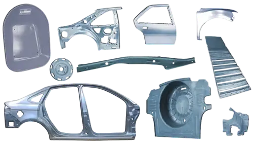
Automotive Stamping Parts
Seat brackets, door hinges, chassis components, heat shields
- High-volume progressive die production
- Tight tolerances for structural assemblies
- IATF 16949 process control & PPAP documentation
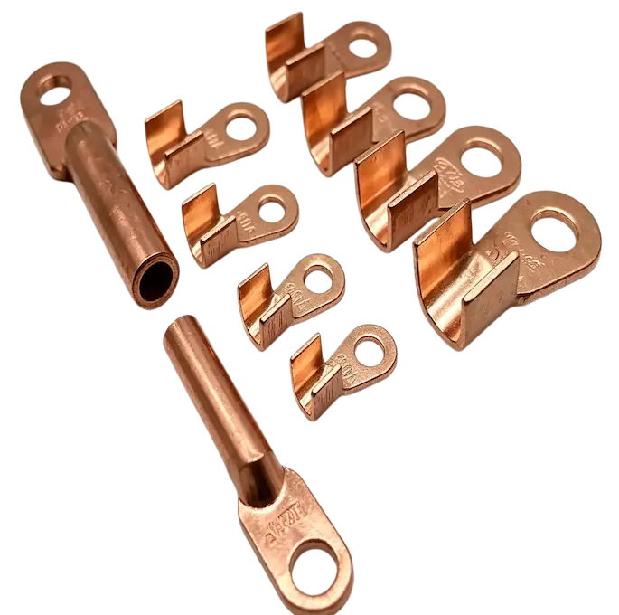
EV & New Energy Stamping
Battery housing components, busbar stampings, motor brackets, EV structural parts
- Lightweight aluminum & high-strength steel stamping
- Fine blanking for battery contact precision
- Scalable from prototype to mass production
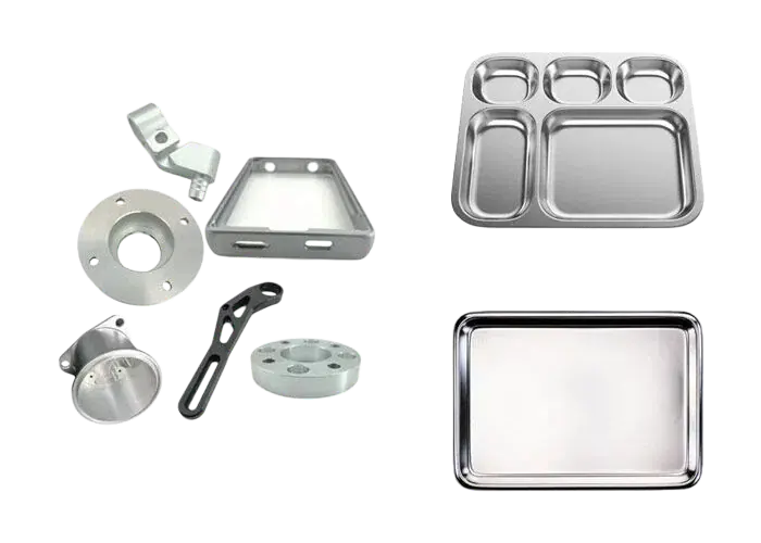
Medical Device Stamping
Surgical instrument components, device housings, implant-grade brackets
- Cleanroom-compatible production on request
- Tight dimensional control — ±0.01mm on critical features
- Full material traceability & inspection documentation

Electronics & Connector Stamping
EMI shields, connector terminals, lead frames, precision brackets
- High-speed progressive die — up to 800 SPM
- Fine blanking for connector contact surfaces
- Copper, brass & stainless steel material capability

Industrial Hardware Stamping
Hinges, brackets, fastener components
- Transfer die capability for deep-drawn hardware
- Multiple surface finishing options
- Flexible MOQ — small batch to mass production

Consumer Appliance Stamping
ppliance panels, inner drum components, heating element brackets, motor housings
- High-volume blanking & forming production
- Consistent surface finish across large runs
- Cost-optimized tooling for consumer price points
Can’t Find Your Part Type? Send us your drawing today for a free DFM analysis and quotation.
We manufacture a wide range of custom metal stamping components beyond the examples shown here. Whether you have a 2D drawing, 3D model, or concept sketch, our engineering team can review your project and provide expert manufacturing feedback.
Our Custom Metal Sheet Stamping Capabilities
Whether you need high-speed progressive stamping for connector terminals, deep drawn housings for EV battery modules, or fine blanking for transmission components — our press shop and in-house tool room are set up to handle it under one roof.
60–300T
Machine Tonnage Range
0.1–10mm
Material Thickness
50M+
Annual Production Capacity (pcs)
±0.01mm
Stamping Tolerance

Metal Stamping Press
60T to 300T press range covering small precision parts to large structural components. Strip width up to 400 mm. Material thickness 0.1 mm to 10.0 mm across steel, stainless, aluminum, copper, and brass.
Strip width Up to 400 mm
Press speed Up to 800 SPM
Part size Up to 800 × 500 mm
Thickness range 0.1 – 10.0 mm
Annual output 50,000,000+ pcs/year

Metal Stamping Process
Six core stamping processes, all in-house — matched to your part geometry, material, and production volume from the first DFM review.
Progressive Die Stamping — high-speed, multi-station, minimal scrap
Transfer Die Stamping — large parts, deep draw, free-state forming
Compound Die Stamping — single-hit, blanking + piercing combined
Blanking Die Stamping — ±0.01 mm, smooth shear face, no secondary ops
Deep Drawn Stamping — housings, shells, cups up to 150 mm draw depth
Coining Die Stamping — tight flatness, controlled springback

Quality Metal Stamping
IATF 16949 certified facility — not just ISO 9001. Every production program runs with in-process SPC monitoring, CMM first-article inspection, and PPAP Level 3 documentation as standard.
PPAP Level 3 capable
General tolerance ±0.05 mm
Fine blanking tol. ±0.01 mm
FAI report Issued with every T1 sample
Cpk requirement ≥ 1.33 on critical features
Not sure if your part fits?
Send us the drawing — our engineers will assess material, process, and tolerance feasibility within 24 hours. No commitment required.
Complete Manufacturing Support Beyond Stamping Die
Stamping is rarely the last step. To reduce your supplier count and simplify logistics, we offer a full range of secondary operations in-house — from precision CNC machining and tapping to surface finishing and sub-assembly. One supplier, one shipment, one point of contact.

CNC Machining
Critical bores, mating faces, threaded features, and tight-tolerance dimensions that stamping alone cannot achieve. Milling, drilling, tapping, and reaming on stamped components without re-fixturing to a second supplier.
Tolerance ±0.005 mm on machined features
Equipment 3-axis & 5-axis CNC machining centers
Best for Automotive brackets, medical housings, connector bodies

Surface Finishing
Enhance corrosion resistance, surface hardness, and appearance with finishing options applied after stamping and machining. All finishing specified and coordinated by our team — no separate finishing vendor required.
Tolerance ±0.005 mm on machined features
Options Zinc plating · Nickel plating · Chrome plating
Powder coating · E-coating · Anodizing (aluminum)
Passivation (stainless) · Black oxide · Dacromet

Deburring & Edge Treatment
Stamped edges carry burrs, sharp corners, and rollover that affect fit, function, and safety. We remove flash and condition edges through vibratory finishing, tumbling, and manual deburring — matched to your part geometry and surface requirement.
Methods Vibratory finishing · Tumble deburring · Manual deburring
Best for Parts with tight mating fits, medical components, consumer-facing surfaces

Welding & Joining
Spot welding, projection welding, and MIG/TIG welding for stamped assemblies that require permanent joining before delivery. Reduces your inbound parts count and assembly labor at your facility.
Processes Spot welding · Projection welding · MIG · TIG
Best for Automotive sub-assemblies, brackets, structural frames, enclosure panels

Tapping & Thread Forming
In-line or post-press tapping for M2 through M16 threads. Thread forming preferred over cutting for higher thread strength in thin-wall stamped parts. Eliminates the need for separate nut insertion in many assembly applications.
Range M2 – M16
Method Thread forming & thread cutting
Best for Sheet metal enclosures, brackets, structural assemblies
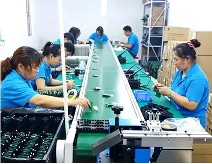
Assembly & Kitting
Mechanical assembly, hardware insertion, fastener installation, and functional sub-assembly completed before shipment. Receive production-ready components — not loose stampings that require further handling on your line.
Services Hardware insertion · Fastener installation
Sub-assembly · Functional testing · Kitting & labeling
Best for Automotive modules, medical device sub-assemblies, electronics enclosures
Why Source Secondary Operations from One-Stop Stamping Supplier?
Managing stamping, machining, finishing, and assembly across separate
vendors multiplies lead time, increases communication risk, and makes quality accountability unclear. At Senses Mold, every secondary operation runs within the same quality system — same IATF 16949 process control, same CMM inspection, same project team from first DFM to final shipment.
Why Global Buyers Choose Senses Mold for Metal Stamping Die?
Sourcing stamped parts from China comes with real risks — dies that wear out ahead of schedule, tolerances that drift in mass production, and tooling you can’t transfer if something goes wrong. Here’s how we’re built to handle each one.

01
Die Life Committed Before Tooling Starts
We document expected tool life before cutting steel — steel grade, heat treatment, and coating selected for your specific material and volume. No surprises after you’ve paid for tooling.
D2 · DC53 · SKD11 · Carbide inserts available
02
Tolerance Held at Shot 500,000, Not Just T1
SPC monitoring on critical features throughout mass production. Press force, feed length, and die temperature tracked in real time. Cpk ≥ 1.33 maintained — not just passed at first article.
SPC · Cpk ≥ 1.33 · Scheduled CMM re-verification
03
Tooling and Production Under One Roof
We build the die and run production on the same floor. If something drifts in production, the engineers who built the die are standing next to the press.
In-house tool room · In-house press shop · One team accountable
04
Your Tooling Is Fully Documented and Transferable
Every die leaves with full documentation — drawings, steel certs,heat treatment records, and maintenance logs. Your tooling, your records, no negotiation.
Die drawings · Steel certs · Heat treatment records
05
IATF 16949 Quality System
Held by fewer than 5% of Chinese stamping manufacturers. Means structured PPAP, control plans, and FMEA as standard — recognized by automotive and medical OEM procurement without additional audits.
IATF 16949 · PPAP Level 3 · FMEA · Control Plan
06
DFM That Prevents Problems Before Steel Is Cut
Springback, splitting, and burr are designed in before the die is built. Our free DFM review flags every stampability risk upfront — when fixes cost nothing.
Springback analysis · Strip layout · Blank optimization
Ready to verify it yourself?
Send us your drawing — get a free DFM review in 24 hours. No commitment required. Our engineers will assess your part for castability and flag any design risks before you invest in tooling.
Complete Metal Stapming Process Step By Step
A stamping program lives or dies at the tryout stage. Most delays and cost overruns in metal stamping happen not because of bad design or bad steel — but because nobody caught the problems before the die was built. Our process is structured to front-load engineering so tryout is confirmation, not discovery.
DFM & Process Planning
Week 1Stampability Assessment
Part geometry reviewed against stamping limits — minimum bend radius, hole-to-thickness ratio, and feature proximity to bend lines. Design risks flagged before any tooling cost is committed.
Strip Layout & Blank Optimization
Blank nesting, carrier width, pilot hole placement, and progression pitch optimized before die design begins. Material utilization locked in at this stage — not after steel is ordered.
Die Type & Process Route
Progressive, transfer, compound, or fine blanking selected based on part size, draw depth, tolerance, and annual volume. Wrong selection at this stage locks in cost problems for the life of the program.
Die Design & Manufacturing
Weeks 2–5Station Sequence Design
Cutting forces distributed evenly across stations. Forming operations staged to control springback progressively — not attempted in a single hit. Weak steel sections between adjacent punches eliminated in design.
Die Component Machining
Punches, die plates, and inserts machined to ±0.002 mm using Wire EDM and CNC grinding. Punch-to-die clearance held to 5–10% of material thickness per side. Components hardened to 58–62 HRC and double-tempered before assembly.
Die Assembly & Bench Setting
Stripper spring force calculated for material and press speed. Shut height set and locked. Die run by hand before first press hit — interference and binding caught at bench, not during tryout.
Validation & Process Lock
Weeks 5–6First Hit Assessment
Initial hits on scrap material before customer stock is used. Strip feeding, pilot engagement, and part ejection verified station by station before full progression is run. Burr height, breakthrough, and strip lifting assessed before dimensional check.
CMM Inspection & Die Correction
First article parts measured on CMM against all drawing dimensions. Springback corrected by over-bending calculated from material tensile data. Every correction documented with before-and-after measurement data — not trial and error.
Speed Ramp & Process Window Lock
Press speed ramped to production rate in increments. Feed accuracy, die temperature, and part ejection monitored at each step. Production speed set at highest stable rate. Process window documented — speed, feed tolerance, lubrication rate, and shutdown criteria.
Mass Production & Delivery
Week 7 onwardSPC Monitoring & Die Maintenance
Critical dimensions charted every 500–1,000 shots. Press force signature monitored in real time — a shift indicates punch wear or lubrication breakdown before parts go out of tolerance. Die cleaned and inspected at scheduled intervals, not on failure.
Secondary Operations
Tapping, deburring, CNC machining, surface finishing, and sub-assembly completed in-house in sequence. No parts transferred to external subcontractors between operations. Same quality system applies from press to final packaging.
Final Inspection & Shipment
Outgoing inspection to agreed AQL. Critical dimensions re-verified on CMM for first production shipment and after any die maintenance event. CoC, material certs, and PPAP documentation issued with every shipment.
Want to know where your project fits in this process?
Send us your drawing — we’ll identify the critical path items and give you a realistic phase-by-phase timeline within 24 hours.
Die Molds Structure Explained
A progressive die is more than punches and a die plate. Every internal system — feeding, guiding, cutting, stripping, ejecting — directly determines part accuracy, strip stability, and tool life. Here’s what’s inside every progressive die we build.
- Die Set & Guide Posts
- Stock Lifters
- Stripper Plate
- Strip Guide & Feed Rails
- Pilot Pins
- Cutoff & Part Ejection
- Punches & Die Inserts
- Carrier & Part Connection
Building a New Progressive Die?
Tell us your part geometry, material, and annual volume —
our engineers will map out station sequence, carrier design,
and steel selection before a single component is machined.


Stamping Die Types — Matched to Your Part and Production Requirements
The die type you choose determines cycle time, part quality, tooling cost, and production flexibility for the life of the program. Here’s how we match die type to your specific part geometry, tolerance, and volume — and why the wrong choice at this stage is expensive to reverse.
Progressive Die
Strip feeds through multiple stations in one die set. Blanking, piercing, bending, and forming happen simultaneously across stations — part stays on the carrier until final cutoff.
Thickness 0.1 – 3.0 mm
Speed Up to 800 SPM
Advantage Lowest cost-per-part at high volume
Limitation Not suited for deep draws or large parts
Best for Connector terminals, brackets, electronic shields
Transfer Die
Blank is cut free at station one and transferred part-by-part through forming stations. Enables deep draws and complex 3D geometry that cannot be held on a carrier strip.
Thickness 0.8 – 10.0 mm
Draw depth Up to 150 mm
Advantage Only viable option for deep drawn structural parts
Limitation Lower SPM, higher cost per part at low volumes
Best for Automotive structural parts, EV battery housings
Compound Die
Blanking and piercing in a single stroke. Hole-to-edge relationship set by die geometry — not feeding accuracy — giving the tightest positional tolerance for flat parts.
Thickness 0.3 – 4.0 mm
Tolerance ±0.02 mm hole-to-edge
Advantage Best hole-to-edge accuracy of any die type
Limitation Flat parts only — no forming capability
Best for Precision flat blanks, contact plates, gaskets
Fine Blanking
Triple-action press produces smooth, square shear faces to ±0.01 mm. No rollover, no fracture zone — shear face is functional without secondary machining.
Thickness 0.5 – 10 mm
Tolerance ±0.01 mm
Advantage Eliminates grinding on functional surfaces
Limitation Higher tooling cost — justified where shear face
quality is a functional requirement
Best for Gear blanks, transmission plates, brake components
Comparison Table
| Progressive | Transfer | Compound | Fine Blanking | |
|---|---|---|---|---|
| Thickness (mm) | 0.1 – 3.0 | 0.8 – 6.0 | 0.3 – 4.0 | 0.5 – 10.0 |
| Tolerance | ±0.05 mm | ±0.05 mm | ±0.02 mm | ±0.01 mm |
| Draw Depth | Shallow | Deep | None | None |
| Speed (SPM) | Up to 800 | 20 – 60 | 30 – 120 | 10 – 40 |
| Tooling Cost | Medium | High | Low – Med | High |
| Best Volume | High | Med – High | Medium | Med – High |
Not sure which metal sheet stamping die type fits your project?
Send us your drawing — free assessment within 24 hours.
Metal Stamping Materials We Support
Material selection in stamping affects springback, burr height, tool wear rate, and surface condition after forming — not just mechanical properties. Here’s what we run, and what each material means for your tooling and production program.


Cold Rolled Steel
SPCC
DC01
ST12
The most widely stamped material. Consistent thickness tolerance, predictable springback, and good formability across a wide temper range. Surface condition suitable for powder coating, e-coating, and plating without pre-treatment in most applications.
Thickness 0.3 – 3.2 mm
Temper Soft to full hard
Springback Low to moderate — predictable
Best for Automotive brackets, enclosure panels, structural hardware, appliance components
Hot Rolled Steel
SPHC
S235
A36
Lower cost than cold rolled at heavier gauges. Mill scale surface requires shot blasting or pickling before finishing. Higher thickness tolerance variation than cold rolled — dimensional control on critical features requires post-stamp machining in some applications.
Thickness 1.5 – 6.0 mm
Temper As-rolled
Springback Moderate
Best for Heavy structural brackets, frames,
industrial hardware, non-cosmetic structural parts
Stainless Steel
SUS304
SUS316
SUS301
Work-hardens rapidly during forming — springback is higher and less predictable than mild steel. Punch-to-die clearance must be tighter than for carbon steel to control burr. Tool wear rate significantly higher — carbide inserts specified for piercing stations on stainless programs above 500,000 shots/year.
Thickness 0.1 – 3.0 mm
Tool wear 3–5× higher than cold rolled steel
Best for Medical device components, food equipment parts, marine hardware, connector shields
Aluminum
AL1050
AL5052
AL6061
Lightweight with good corrosion resistance. Galls against steel tooling at high speeds — lubrication strategy and die surface coating are critical. AL5052 offers better formability than AL6061; AL6061 gives higher strength but cracks on tight bend radii without adequate temper selection.
Thickness 0.5 – 10.0 mm
Springback Moderate to high depending on temper
Best for EV battery structural parts, electronic housings, lightweight automotive brackets
Copper & Brass
C1100
C2680
C2600
C5191
High electrical conductivity makes copper and brass thedefault for connector terminals and contact parts.
Work-hardens quickly — station sequence must stage forming to avoid cracking at tight radii. Surface finish after stamping is critical for plating adhesion on contact surfaces.
Thickness 0.1 – 10.0 mm
Tool wear Moderate — abrasive at high speed
Conductivity High — primary selection driver for contacts
Best for Connector terminals, contact springs, lead frames, electrical busbars
High Strength Steel
HSLA
DP590
DP780
DP980
Increasing use in automotive lightweighting programs.
Springback is significantly higher than mild steel and
harder to predict — die compensation requires iterative tryout or FEA simulation upfront. Press tonnage requirement is higher for the same thickness. Tool wear accelerates above DP780 — die steel and coating selection critical for program life.
Thickness 0.8 – 3.0 mm
Springback High — FEA simulation recommended
Press tonnage Higher than equivalent mild steel
Best for Automotive structural parts, crash members,
EV battery enclosure frames
Not sure which material specification fits your application?
Share your part requirements — we’ll recommend material grade, temper, and thickness, and flag any forming or tool wear implications before tooling starts.
Stamping Design Guidelines for Better Parts and Lower Tooling Cost
Most stamping problems are designed in before the die is built. Four design decisions account for the majority of DFM failures we see — get these right early and you’ll avoid costly tool rework and production delays.

Bend Radius
Most common DFM issue
Minimum inside bend radius: 1× material thickness for coldrolled steel, 1.5–2× for stainless and hard temper aluminum. Bending across grain direction allows tighter radii — blank orientation in strip layout should account for this.

Hole-to-Edge & Hole-to-Bend Clearance
Affects dimensional stability
Hole-to-edge minimum: 1.5× material thickness. Hole-to-bend minimum: 2× material thickness + bend radius.
Violations require secondary piercing after forming — adding a station and cost.

Springback Compensation
Affects angular tolerance
All sheet metal springs back after forming. High strength steel and stainless can spring back 10–15° on a 90° bend. Uncompensated springback means die correction after T1 – adding lead time and tooling cost.

Minimum Web Width
Affects tool life
Minimum web between adjacent holes: 1.5× material thickness. Narrower webs create fragile die sections prone to chipping and require carbide inserts to maintain tool life.
Want the complete design guidelines?
Upload your drawing — free DFM check against all four criteria.
Steel Stamping Die Material Selection
The steel your die is made from determines tool life, edge quality, and total tooling cost over the program. We select die steel based on your material, volume, and tolerance —not a default.

- D2
Cold-work tool steel · AISI D2
Hardness 58–62 HRC
Tool life 300,000–800,000 shots
Best for General blanking & piercing, medium volume
The standard choice for most progressive and compound dies. Good wear resistance and toughness balance at a moderate cost. Works well across mild steel, aluminum, and copper alloys.
- DC53
Improved cold-work steel · Japanese grade
Hardness 60–62 HRC
Tool life 800,000–1,500,000 shots
Best for High-speed progressive dies, stainless steel
Higher toughness than D2 at the same hardness — resists chipping at sharp punch corners during high-speed stamping. Our default for stainless steel and high-volume programs.
- SKD11
Japanese cold-work steel · Equivalent to D2
Hardness 58–62 HRC
Tool life 300,000–800,000 shots
Best for Precision blanking, fine blanking dies
Tighter manufacturing tolerance than standard D2 — more consistent hardness across large die blocks. Preferred for fine blanking and high-precision compound dies.
- Tungsten Carbide
Cemented carbide inserts
Hardness 90+ HRA
Tool life 5,000,000+ shots
Best for Stainless, copper, abrasive materials, ultra-high volume
Highest wear resistance of any die material. Used for piercing punches and inserts on abrasive materials or programs above 2 million shots — significantly reduces maintenance frequency despite higher upfront cost.
Surface Treatments — Applied to All Steel Grades
- Gas Nitriding
+20–30% surface hardness, resists galling
- PVD Coating
TiN / CrN / AlTiN — reduces friction & wear
- Mirror Polishing
Improves shear face quality on fine blanking
- Cryogenic Treatment
Improves dimensional stability at hardness
| Property | D2 | DC53 | SKD11 | Carbide |
|---|---|---|---|---|
| Tool Life | ||||
| Toughness | ||||
| Edge / Shear Quality | ||||
| Cost Efficiency | ||||
| Best For | General Blanking & Piercing |
High-Speed & Stainless |
Fine Blanking & Precision |
Ultra-High Volume |
Not sure which steel grade fits your program?
Tell us your material, thickness, and annual volume — we’ll recommend the right grade before die design begins, at no cost.

Custom Metal Die Stamp Advantages and Disadvantages
Metal stamping is one of the most efficient processes for producing high volumes of precision sheet metal parts. Understanding where it excels — and where it doesn’t — helps you make the right sourcing decision for your project.
Advantages of Metal Stamping
- High Production Efficiency: Progressive dies run up to 800 strokes per minute — the most economical process at volume.
- Excellent Repeatability: Once proven out, dimensional consistency holds across millions of cycles.
- Low Material Waste: Optimized strip layout typically achieves 70–85% material utilization.
- Wide Material Compatibility: Steel, stainless, aluminum, copper, and brass all run on the same tooling approach.
- Minimal Secondary Processing: Fine blanking and compound dies can produce finished surfaces directly.
- Strong Cost Scaling: Fixed tooling cost means unit cost drops sharply as volume increases.
Disadvantages of Die Casting
- High Upfront Tooling Cost: Progressive and transfer dies require significant investment before first shipment.
- Less Economical at Low Volumes: Below a few thousand pieces, laser cutting or CNC may cost less.
- Design Changes Are Expensive: Geometry changes mean reworking or rebuilding the die.
- Springback Is Hard to Predict: High strength steel and stainless need iterative tryout or simulation.
- Limited to Sheet & Strip Form: Not suited for solid or thick-section parts.
- Tool Wear Affects Consistency: Without scheduled maintenance, dimensions and edge quality drift over time.
Not sure if stamping is right for your part?
Send us your CAD files for a free manufacturability review.
Custom Stamping— Complete Process & Materials Guide
Everything you need to know about metal stamping — design, materials, cost, defects, process comparisons, and supplier selection. Each link goes to a dedicated deep-dive article. Start wherever your question begins.
- Design & Engineering
7 Metal Stamping Design Mistakes That Cost You a Die Rework
Bend Radius in Sheet Metal Stamping: The Complete Engineer’s Guide
Springback in Metal Stamping: Why It Happens and How to Compensate
Hole-to-Edge Clearance in Stamping: Rules That Prevent Distortion
- Defects & Troubleshooting
Burr in Metal Stamping: Causes, Measurement & Prevention
Metal Stamping Defects: A Visual Troubleshooting Guide
Why Are My Stamped Parts Cracking? (And How to Fix It)
Strip Feeding Problems in Progressive Dies: Diagnosis Guide
- Materials & Selection
Cold Rolled vs Hot Rolled Steel: Which Should You Specify?
Stainless Steel Stamping: Springback, Tool Wear & Design Tips
Aluminum vs Steel Stamping: How to Choose for Your Part
D2 vs DC53 vs Carbide: Choosing Die Steel for Long-Run Programs
- Cost & Manufacturing
How Much Does a Progressive Die Cost? (2026 Pricing Guide)
Metal Stamping Cost Breakdown: What You’re Actually Paying For
Metal Stamping Lead Time: From RFQ to First Shipment
Progressive Die vs Laser Cutting: Real Cost Comparison at Volume
- Process Comparisons
Progressive Die vs Transfer Die: Which Process Fits Your Part?
Fine Blanking vs Conventional Blanking: When the Extra Cost Is Worth It
Metal Stamping vs CNC Machining: Which Wins at Your Volume?
Deep Drawing vs Hydroforming: A Buyer’s Decision Framework
- Supplier Selection
Stamping Die Ownership: What Happens If You Switch Suppliers
In-House vs Outsourced Tooling: Why It Matters for Stamping Programs
PPAP for Metal Stamping: What Automotive Buyers Should Require
Metal Stamping Capacity Audit: What to Check Before You Commit Volume
Explore our other tooling and manufacturing capabilities:
Senses Mold offers complete tooling and manufacturing solutions for metal, plastic, silicone, and rubber components.
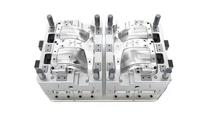
Injection Mold ↗
Custom injection molds for plastic part production manufacturing.
Production Tooling ↗
Production-grade tooling for reliability, consistency, and long mold life.
Prototype Tooling ↗
Cost-effective tooling for design validation, testing, and pilot production.
LSR Mold ↗
Precision LSR molds for stable silicone molding and repeatable production.
Compression Mold ↗
Custom compression molds for rubber & silicone component manufacturing.
Transfer Mold ↗
High-precision transfer molds for complex rubber and thermoset applications.
Frequently Asked Questions About Metal Stamping
Metal stamping forms sheet metal using a die and press through blanking, piercing, and bending — the material stays solid throughout. Die casting injects molten metal into a die cavity under pressure. Stamping suits flat or formed sheet parts; die casting suits complex 3D geometries with internal features.
A stamping die is a precision tool mounted in a press that cuts and forms sheet metal into a finished shape. Dies range from single-station tools to progressive dies with up to 60 stations performing multiple operations in sequence.
In a progressive die, the part stays connected to the strip until the final station. In a transfer die, the blank is cut free at the first station and moved part-by-part through forming stations — required for deep draws and large parts that can't be held on a strip.
Cost depends on part complexity, number of stations, and material thickness. Simple dies with 5–10 stations typically range from a few thousand to low tens of thousands of dollars; complex high-station dies for automotive parts can run higher. Send your drawing for an accurate quote.
Most progressive and transfer dies take 4–6 weeks from design approval to T1 sample, depending on station count and complexity. Simple compound dies can be faster.
Yes. Stainless steel work-hardens faster than mild steel and has higher springback, so die clearance and steel grade are adjusted accordingly — typically DC53 or carbide inserts for piercing stations on stainless programs.
We support prototype runs through high-volume production. Low-volume programs may use simpler tooling or compound dies to keep upfront cost manageable.
Yes, free of charge. We review bend radius, hole clearance, springback allowance, and strip layout before any die design work begins.
Fine blanking uses a triple-action press to produce parts with smooth, square shear faces to ±0.01 mm — without secondary grinding. It's used when the cut edge is a functional surface, such as gear blanks or transmission components.
Cold rolled and hot rolled steel, stainless steel, aluminum, copper, brass, and high strength steel grades. Material choice affects springback, tool wear, and achievable tolerance.
Burr is typically caused by excessive punch-to-die clearance,
worn punches, or incorrect material hardness for the specified
clearance. It's corrected by adjusting clearance or replacing
worn die components.
Yes. We regularly export to North America and Europe, with English-speaking project managers and export-compliant documentation included.
Blanking cuts the outer profile of a part from the strip — the cut piece is the part. Piercing cuts internal features like holes or slots — the cut piece is scrap, and the surrounding material is the part.
Ready to Discuss Your Metal Stamped Parts?
From stamping die design and tool manufacturing to production, secondary operations, and assembly, Senses Mold provides complete
support for your project.
✔ Free DFM Review
✔ Fast Quotation Within 24 Hours
✔ Tooling & Production Under One Roof